 Facebook
 Google
 GitHub
 Linkedin
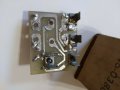
I'm a collector of old tools and I just picked up an early 1970s Milwaukee Electric mag drill for $50 which is quite cheap. Only issue is it is missing the control panel which has been discontinued for some time now. I was able to find the control board on ebay but the seller wants $250 for it which to me is insane. Good thing is he took great pictures of the board and I found some other pictures online to where I can just about replicate the circuit. I've attached all the pictures I have. Ignore the DPDT switch on the right of the board as that is for motor forward and reverse, which is already figured out.
The 120V AC signal goes into a VH247 rectifier (6A 200V rating) and the two outputs go into nodes 1 and 2 (middle terminals of DPDT switch).
When the switch is turned to the ON position it connects 1 and 2 to A and B which go to the magnetic coil (measured resistance is 106.8 ohms). In parallel is a 250V 100uF capacitor for ripple smoothing. 27K resistor is also in parallel.
Also in ON, it seems current flows from A to D via a 2.2k ohm resistor and then from D to one of the AC inputs through a 56k ohm resistor and an lamp.
In LTspice, I modeled a 170 PP 60 Hz signal. I also used 4 voltage controlled switches to act like the DPDT switch. They are controlled by a pulse signal that essentially simulates the switch being flipped to ON for 2 seconds, then OFF for 1 second, and then to DEMAG for 2 seconds. I also modeled the coil as a resistor at the point of 106 ohms (don't know the inductance as I don't have an LCR to measure it with).
What I've gathered:
When ON the coil gets a voltage that ripples from 167V to 104V at 60Hz.
When OFF the coil/capacitor drop to 0V in about 125ms.
When DEMAG is selected the coil sees a negative voltage that ripples from -4.5 to -5.2
My biggest concern/interest is in the indicator lamp. It gets it's current from terminal A through a 2.2k ohm resistor then to a 56k ohm resistor, through the lamp and then connects to one of the AC input lines. The 58.2k series resistance severely limits the current flow to this lamp. How can this lamp light up? Even at 0 ohms resistance, it can only flow about 3ma. What am I missing here?
.jpg")
.jpg")


The 120V AC signal goes into a VH247 rectifier (6A 200V rating) and the two outputs go into nodes 1 and 2 (middle terminals of DPDT switch).
When the switch is turned to the ON position it connects 1 and 2 to A and B which go to the magnetic coil (measured resistance is 106.8 ohms). In parallel is a 250V 100uF capacitor for ripple smoothing. 27K resistor is also in parallel.
Also in ON, it seems current flows from A to D via a 2.2k ohm resistor and then from D to one of the AC inputs through a 56k ohm resistor and an lamp.
In LTspice, I modeled a 170 PP 60 Hz signal. I also used 4 voltage controlled switches to act like the DPDT switch. They are controlled by a pulse signal that essentially simulates the switch being flipped to ON for 2 seconds, then OFF for 1 second, and then to DEMAG for 2 seconds. I also modeled the coil as a resistor at the point of 106 ohms (don't know the inductance as I don't have an LCR to measure it with).
What I've gathered:
When ON the coil gets a voltage that ripples from 167V to 104V at 60Hz.
When OFF the coil/capacitor drop to 0V in about 125ms.
When DEMAG is selected the coil sees a negative voltage that ripples from -4.5 to -5.2
My biggest concern/interest is in the indicator lamp. It gets it's current from terminal A through a 2.2k ohm resistor then to a 56k ohm resistor, through the lamp and then connects to one of the AC input lines. The 58.2k series resistance severely limits the current flow to this lamp. How can this lamp light up? Even at 0 ohms resistance, it can only flow about 3ma. What am I missing here?
Attachments
-
 242.4 KB Views: 41
 -
 164.1 KB Views: 39
 -
 219.5 KB Views: 42
 -
 154.7 KB Views: 40
 -
 164.4 KB Views: 39
 -
3.7 KB Views: 6


