Help me figure out this Magnetic Drill Base Control Circuit

Thread Starter

sheltonfilms

Joined Feb 11, 2020
12
Your luck is like most of mine when looking for information from what mrbill calls reputable companies. He says he has better results so maybe he will get in touch with them for you?
Not to get off track here but MrBill is right about some companies. Only issue is Milwaukee Electric Tool Corp was sold multiple times from the time this tool was made until now. Usually those companies purge old records from what I've seen, especially if locations change, or they get lost. Now they are a China owned brand.

Rheem is good company for getting information. I had an issue with one of their tankless water heaters (issue wasn't with heater but a gas regulator). Called them up and told them my issue. They asked if I was the homeowner and I said yes. Then the guy says do you feel competent in doing work yourself? I was shocked by this. I answered yes. He then asks me "do you want me to walk you through the steps or would you like me to email you the service manual at no charge?" I took the service manual and got my problem fixed using their troubleshooting chart. Couldn't believe it.
 

Thread Starter

sheltonfilms

Joined Feb 11, 2020
12
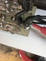
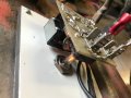
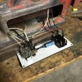
I found a circuit board on ebay and it was a good enough price to buy it instead of making one. I had to add a DPDT switch to the board, and after I soldered it on I wanted to test it. As soon as power was provided, it instantly blew a trace from the main power input to the input of the FWR. I checked the FWR and it was shorted between the two inputs. Ok board was a dud. This FWR was a VH347 (6A 200V) and the board was probably 50 years old.

Bought a KBPC602 FWR (6A 200V) to replace the old one. Also used copper foil tape to repair the blown trace. Got everything soldered up and tested and it worked fine. Added the capacitor and connected to the coil and it worked great. Test it multiple times.

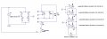
At one point, I forgot to turn off the magnet and it sat for maybe 5 minutes. (the magnet wasn't attached to metal if that makes a difference). All of a sudden a flash could be seen behind the board and a pop. It blew the trace again and once again the FWR was shorted out. This trace would be on the schematic of V1 on the "negative" side (where ".trans 5" is located).

Did I just get another bad rectifier? Is something causing high reverse voltage?

Also to again to explain the circuit below. When the unit is turned on 1 connects to A and 2 connects to B. (the other part of the DPDT is for demagnetizing the base). R5 is the coil ( i just put it in as a resistive load). Machine plate says this system has a 1.5 Amp current draw.

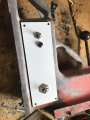
BONUS Question: Are neon lights suppose to be that dim? Do they get dimmer with age? Can barely see it in the jeweled indicator lens.

Circuit.JPG
Photo Mar 30, 10 34 28 AM.jpg
 

Attachments

AlbertHall

Joined Jun 4, 2014
12,636
Neons do get dimmer with use. The glass envelope gradually darkens, I guess because some of the metal from the electrodes is sputtered onto it.
How is that 100uF capacitor? They also get 'weak' with age.
 

Thread Starter

sheltonfilms

Joined Feb 11, 2020
12
Neons do get dimmer with use. The glass envelope gradually darkens, I guess because some of the metal from the electrodes is sputtered onto it.
How is that 100uF capacitor? They also get 'weak' with age.
The capacitor didn't come with the board and it was either new or NOS. Measured right on the money with my multimeter for capacitance.

Ok, so I'll order a new neon bulb. Still wondering on why that FWR shorted. Original design never called for attachment to aluminum for heat sinking. May step up to a 8A 400v one a attach it to some aluminum unless someone thinks it's something else messing it up
 

MisterBill2

Joined Jan 23, 2018
27,759
Capacitors do develop leakage as they age, and sometimes they develop breakdowns. and there is also a fair chance that the bridge rectifier is running close to it's limits and overheating. Some equipment designs have a duty cycle limit, one minute on and ten minutes off. And a rectifier good for 6 amps may only be good for that with a serious heat sink for continuous operation. Heat accumulates and temperatures rise and failure can certainly result. All this from both experience and study.
 

Wolframore

Joined Jan 21, 2019
2,619
I have an old electromagnetic chuck pretty much given to me but the power supply was old and shot... it was originally diode tubes. I put in a rectifier and large capacitors and it’s back in service. I put in a neon bulb under the old gem light. To demagnetize I just rock the switch. A new power supply was available for $600. its a hefty Magnalock for surface grinding a new one costs up to $6k.

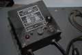
Heres what the power supply looks like. The brass switch was very interesting Inside.
1585714793307.jpeg
 
Last edited:

Thread Starter

sheltonfilms

Joined Feb 11, 2020
12
Cool unit. Got pictures of what it looked like inside?

I'm starting to think I may have damaged the rectifier by using the soldering iron on it too long. I kept having problems with soldering sticking to the leads and it turns out there was some sort of coating on it. During this process I think I probably keep the iron on it too long and could have caused damage.
 

Wolframore

Joined Jan 21, 2019
2,619
I don’t have pictures of the innards, it’s really embarrassingly easy. Just a rectifier and cap off the transformer. The case is much bigger than it needs to be due to the space they had for tubes. I love the look of it, looks like mad scientist switch.
 

MisterBill2

Joined Jan 23, 2018
27,759
OK, Wolf, the fact that it originally had tube rectifiers alters the situation a whole lot. I am thinking now that there were only two tubes and that it was simply a full wave rectifier with a center tapped transformer. If that setup had a bridge rectifier installed instead, using the ends of the transformer secondary winding, the voltage would be more than twice as much. Not only from the bridge circuit but also because of the much lower forward voltage drop through the bridge diodes. And at twice the voltage that may have exceeded the filter capacitor rating. And it may also have been a bit beyond the bridge diodes rating. BUT all of this is based on the presumption that the original circuit only had a full wave rectifier circuit.
 

Wolframore

Joined Jan 21, 2019
2,619
Its been about 5 years since I did this.. works great, but its not centertapped and since most of it was missing no clue what tube was in it, sorry I meant tube not tubes. I vaguely recall checking the DC output and it was fine, in fact it doesn’t even get warm. It’s only about 500 mA. I put in a full wave (I think I used 1N4007 or similar) and dont recall the sizing of the cap but that’s a good point about the difference of center tapped two diode rectifiers.
 
Last edited:

MisterBill2

Joined Jan 23, 2018
27,759
Its been about 5 years since I did this.. works great, but its not centertapped and since most of it was missing no clue what tube was in it, sorry I meant tube not tubes. I vaguely recall checking the DC output and it was fine, in fact it doesn’t even get warm. It’s only about 500 mA. I put in a full wave and dont recall the sizing of the cap but that’s a good point about the difference of center tapped two diode rectifiers.
OK, and good. Just a bit of confusion, it was the other magnetic base in this thread that had the problem. Just a bit of tangled thread, it seems.
 
Top