Please help me to figure out this

Thread Starter

PAMATH

Joined Sep 18, 2025
1
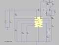
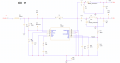
Hi im, new to power electronics and i did a simple boost converter using IC LT8361 IC (SEPIC TOPOLOGY). VIN = 12 V, VOUT+= +60v, VOUT-= -60V. I'm getting proper results in LTspice but thinking that im correct i just proceeded with fabricating the PCB for the same, But now im not getting Output from the above circuit. Vout both rails 0V. PLease help me.
 

Attachments

ericgibbs

Joined Jan 29, 2010
21,390
Hi PAMATH,
Welcome to AAC.
Please post your LTSpice asc file also photo-shot of both sides of your PCB, we can then check for any errors.
E
 

MisterBill2

Joined Jan 23, 2018
27,164
What Pamath needs to understand is that simulators are often different from the real world. In a simulator that most beginners use, resistors never fail due to overloads, and in a simulator every connection is perfect. And since I do not see any pin numbers in the simulation, the PCB version might be totally random as far as connections go.
 

ronsimpson

Joined Oct 7, 2019
4,646
You have three separate inductors. I have always used coupled inductors or a transformer.
You need a command like this. .K L1 L2 L3 1
And you need inductors with dots in the end.

Look at help to see how to couple inductors.

This is an example of a very different supply but shows a transformer.
1759339159256.png
 

MisterBill2

Joined Jan 23, 2018
27,164
One additional fact is that creating a complete design of a switch-mode power supply is probably the most complex of any basic electronic block. The reason is that even after a "perfect circuit" is actually designed, the physical arrangement is just as complex and demanding, because every connection is also a circuit element with inductance and resistance.
 

ronsimpson

Joined Oct 7, 2019
4,646
Don't worry about "this is hard".
Get your SPICE circuit working OR post your file and one of us will fix it.
Then we can think about things that might go wrong. One step at a time.
 
Top