 Facebook
 Google
 GitHub
 Linkedin
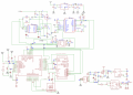
Please help me figure out the connection in this diagram. The picture shows a fitness tracker. The question is: 1. What is the designation near the u11 chip (marked in gray)? 2. How can these three parts of the electrical circuit be connected so that there are no "flying in the air" elements? The circuit itself has an oxygen saturation sensor (u4), an accelerometer(u11), a body temperature sensor (u1), a microcontroller, and a convector. How do I connect the sensor unit to the charging unit correctly?
Attachments
-
1 MB Views: 7
-
 304 KB Views: 33


