I'll give it a go even though I know 0 about opamp circuits or really what it does haha. Will this be accomplishable with a ic and some resistors? I take it that this circuit will go inbetween my vr1 regulator and my vcc on dpm1 (meter)?
No.
The amp goes between the current shunt and the voltmeter input.
The 'Hot' input resistor goes to the shunt terminal connected to the PSU. The 'Cold' input goes to the shunt terminal connected to the load.
As the '7107 needs the input to be above ground, you can use the +3.3V as a 'virtual ground', so the amp ground symbol and the voltmeter negative input connect to the +3.3V. The amp output connects to the voltmeter positive input.
This translates the voltage across the shunt to a voltage above the 3.3V.
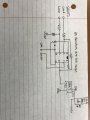
I have attached an image containing a few figures. Figure 1 shows the pinout of an opamp 8pin dip, figure 2 shows the circuit you have described to me (from what I understand), and figure 3 shows (a portion of) the final circuit from what I understand. Also since the datasheet says that the max supply voltage is +18v I'm not sure if it really matters if I use 3.3v, 5v, or 12v lines to supply the opamp.
The connections to the shunt are the wrong way round.
You should use the 12V and COM as the supply to the opamp.
Also with this opamp you may need to use offset null. This is simply a 100k pot connected between pins 1 and 5, with the wiper connected to 0V (COM). The pot is adjusted so the voltmeter reads zero when no current is being drawn.
Should I have my meter set to a miliamp range or an amp range?
(Connections)
Pin1 [null] -> 100k pot -> 0v?
(There's 2 offset null pins on my dip so I'm not sure if I connect it to 0v or just to the other pin) *edit: after checking a similar datasheet I see pin VEE and both of the balance pins connected to the pot so I'm assuming that's how it works. Although the datasheet shows a 10k pot?
Pin2 [inv-input] -> shunt {load}
Pin3 [noninv-input] -> shunt {source}
Pin4 [vee] -> Common
Pin5 [null] -> ?
(The second null pin I previously mentioned)
Pin6 [output] -> positive of dpm1 input
Pin7 [vcc] -> +12v of PSU Supply
Pin8 [NC?] -> N/A
(Not really sure what NC is but I'm sure it doesn't matter for my use case)
{excluding all of the minor connections}
1) The lack of a response means nothing and certainly can't be taken as an endorsement of your design. As you've seen you had a few issues.
2) The level of activity within two hours of making the initial post means nothing -- about a third of the world was asleep during this entire time. Many active members only check the forums once a day or even once a week or less. My first post here didn't get it's first response for about two weeks.
3) The number of views means nothing. Most threads pick up quite a few views and most of them are people skimming the thread and deciding that it is not of interest to them. This is particularly the case when a thread title contains almost no information and, "Help double checking my circuit" certainly qualifies. So you can expect quite a few people viewing the thread just to see what you are going on about and immediately deciding either that they aren't interested or that they don't know enough to comment one way or the other.
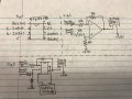
The diagram below shows how to connect the null pot. I can't find a datasheet for the device you're using that shows how to use the nulling connections but I think that chip similar to the LF351 and I have seen datasheets showing 10k and 100k for nulling pot! 10k seems more common so I would go for that - I don't think it will be critical.
NC stands for 'no connection' so you are right to leave it disconnected.
I wanted to quickly extend my appreciation for all the little silly questions you have answered for me as you have been a great help in my explorations of new topics
It seems that the meter should most likely be set back into amp range.
A final circuit is attached for the sake of triple checking.
That circuit looks good to me.
The opamp produces a voltage proportional to the current, so DPM1 should be reading a voltage although the display will represent a current.
 Facebook
 Google
 GitHub
 Linkedin
")