Help design an LVDS splitter

Thread Starter

kaspernordmark

Joined Jan 15, 2019
16
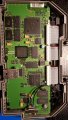
I've got an embedded system
20181218_185737.jpg
that sends out the TTL parallel picture signals to a DS90CR215 chip
20181218_190004.jpg
that converts it to LVDS and then sends it to the screen where a DS90CR216 converts it back into TTL parallel.
20181122_161448.jpg

What I want to do is to split the LVDS signal so that I can connect another identical screen but I can't for the life of me find how to do that?

There is an OEM splitter that does that but is almost impossible to get a hold of. So I know it's possible.
Screenshot_20181015-140957_Chrome.jpg

So how should I design this LVDS splitter? I can't find any chip that does it at least.
It doesn't have to be pretty only functional.
 

Attachments

LesJones

Joined Jan 8, 2017
4,174
If you can situate a second DS90CR216 receiver chip close to the first one I think you should be able to parallel the inputs. How close the two DS90CR216 receiver chips need to be to each other will depend on the transmit clock frequency. NOTE. You must only use one set of terminating resistors.

Les.
 

Thread Starter

kaspernordmark

Joined Jan 15, 2019
16
If you can situate a second DS90CR216 receiver chip close to the first one I think you should be able to parallel the inputs. How close the two DS90CR216 receiver chips need to be to each other will depend on the transmit clock frequency. NOTE. You must only use one set of terminating resistors.

Les.
(If I understood this correctly.)
I am going to have the two screens about 2 meter apart bmw-seria-7-e65-2005-16.jpg
and the sender in the middle
Placement of sender FDlKt5Ck.png
and current location of the screen with receiver integrated in the back of the housing just above the sender FDnq2EWR.png

So I don't know if your suggestion will still work?
 
Last edited:

LesJones

Joined Jan 8, 2017
4,174
I don't think I understood your system. I imagined there was a long distance between the source of the signals that were sent over the diferential link but as the pictures show the inside of a car that idea must be wrong. Is it not possilble to just buffer the TTL signals from the existing receiver and feed the buffered signal to two displays ? You could probably make a splitter using one DS90CR216 receiver chip driving two DS90CR215 chips. I have no idea what all the numbers are on your two black and white pictures. The only information I have is the data sheet on the transmitter and receiver chips.

Les.
 

Thread Starter

kaspernordmark

Joined Jan 15, 2019
16
X01073 is probably the only relevant number on those pictures and that is the out connection from the transmitter which runs maybe half a meter up through the arm of the screen holder and in here to the screen driver board at the back of the lcd20181122_161536.jpg to the receiver chip
20181122_161524.jpg
I will have to look into how buffering the signal works.
But I suspect that would mean to first run the lvds line to one of the screens in one backrest and from there run a TTL line from the receiver to the other screen in the next backrest?
 

LesJones

Joined Jan 8, 2017
4,174
The MAX9175 is no use for buffering TTL signals as it is designed for differential signals and TTL is single ended. I also think that 2 metres is too far to send TTL signals if the data rate is high. (Which is something I don't know about your system.) If you decide to try to build a splitter you would have to design and make (Or have manufactured) a printed circuit board that included a 3.3 volt regulated power supply and terminating resistors to match the characteristiv impedance of the differential cable. While looking at the data sheet for the DS90CR215 that it includes a link to an application note on using them in a multi drop configuration. I suggest that you read that as that might be another possible solution.

Les.
 

Thread Starter

kaspernordmark

Joined Jan 15, 2019
16
Okay I'll be sure to read up on that!

The MAX9175 I was thinking to use with the output LVDS signal from the DS90CR215 transmitter in and not the ttl signals.
 

LesJones

Joined Jan 8, 2017
4,174
The problem with the differential signals over long cables is not loading it is reflections. This is why the cable must be terminated correctly. This is why I suggested reading the application note on multi drop configurations. I have reached the limit of my knowledge on this sort of problem but there are probably members of this forum with more knowledge on the subject than me,

Les.
 

Thread Starter

kaspernordmark

Joined Jan 15, 2019
16
Yes and you should have much thanks for the help!
I have red a little on multi drop configuration and it looks promising so I will investigate further into that. I suspect that is how the OEM have done it.
 
Top