H bridge with NPN bipolar transistors

Thread Starter

SimpleThings

Joined Jul 26, 2016
18
Hello everyone ,
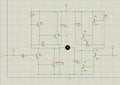
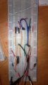
I am trying to build a H bridge for a DC motor of a toy car that I have found from my childhood ,
motor is 6 V I think and I have used BC547 NPN bipolar transistors.
http://html.alldatasheet.com/html-pdf/11551/ONSEMI/BC547/179/1/BC547.html

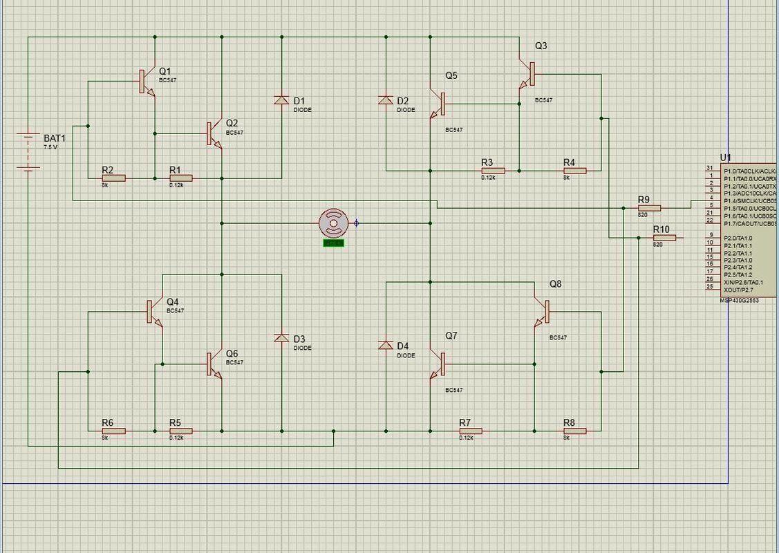
I connected transistors in darlington so I can get current amplified to get the motor running and used two resistors ,
R1 = 120 ohms and R2 = 8k ohms because without them transistors were getting really hot.

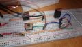
For controlling transistors I use MSP430 microcontroller from texas instruments with ~3.3V DC output on the each digital pin
jpg images

So I am encountering really strange problem for example when I connect battery as on the picture above I get no motors moving one the one darlington pair of the transistors and on the other ones I get motor going but it's just really slow ,
but If I short circuit collector and base electrodes of the any transistor I get motor running at full speed, but since C-E gets forward biased it destroys the transistors eventually.

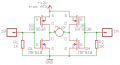
This is what I have measured with the voltmeter , where transistor 1 is getting input from the microcontroller:
img host
image sharing sites

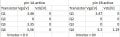
Vce2 = 5.6V , Vbe2 = 0.71V
Vce1 = 6.2 V , Vbe1 = 0.7V
and VRB = 2.36 V ,

where VRB is voltage drop across the base resistor
from the base emitter voltage it seems like both transistors are forward biased,
and base current of the first transistor is Ib1 = VRB/RB = 2.36 / 820 = 2.88 mA which is pretty high current and it should get amplified twice with both transistors.

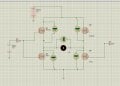
What is more confusing is when I take the battery and connect it to the opposite sides the motor gets going with very low speed, and I measure voltages:
Vce2 = 0-82 V, Vbe2 = -0.19 V
Vce1 = -1.39 V , Vbe1 = -0.87V

I can even disconnect microcontroller pin to feed the base electrode of the first transistor and the motor is still running since the BE is reversed biased.

Would really appreciate your help.
 

Thread Starter

SimpleThings

Joined Jul 26, 2016
18
I forgot to mention that all those voltages were measured with voltmeter on this circuit


Seems like motor can't get enough voltage since Vce voltage drop is pretty high , I guess BC547 isn't really adequate for this circuit or maybe I am wrong?
 

AlbertHall

Joined Jun 4, 2014
12,344
The maximum control input to the transistors in the top of this diagram is 3.3V. You have at least 2*VBE less than that at the motor - about 2V maximum. To use only NPN transistors you need something like this (replace the BD679 with your BC547 darlingtons, and replace the inductor with your motor and the +5 should be the 3.3V uC supply and the + should be your 6V motor supply). This circuit also does not self-destruct if both inputs are active at the same time.
 

Thread Starter

SimpleThings

Joined Jul 26, 2016
18
The maximum control input to the transistors in the top of this diagram is 3.3V. You have at least 2*VBE less than that at the motor - about 2V maximum. To use only NPN transistors you need something like this (replace the BD679 with your BC547 darlingtons, and replace the inductor with your motor and the +5 should be the 3.3V uC supply and the + should be your 6V motor supply). This circuit also does not self-destruct if both inputs are active at the same time.
So I give controlling signals to X and Y terminals from my uC?
 

bertus

Joined Apr 5, 2008
22,270
Hello,

I have some remarks made on your schematic:

h br proteus with comments.jpg

I now also see D1 shorted, so Base-Emittor of Q2 is shorted.

Bertus
 

crutschow

Joined Mar 14, 2008
34,280
What is the motor current?
To apply full voltage to the motor and minimize transistor dissipation, you need to go to a complementary H-bridge with PNP transistors at the top of the bridge.
An NPN darlington stage will give a minimum voltage drop of near 1V from collector to emitter for the bottom transistors and 1.5V for the top transistors, thus the maximum motor voltage will be about 2.5V below the power supply voltage.

The easiest way to build such a bridge is to use complementary logic-level MOSFETs.
 

AlbertHall

Joined Jun 4, 2014
12,344
At the moment you have both X and Y connected directly to the 3.3V supply. If the uC output produces 0V and 3.3V outputs then you do not need the connection to the 3.3V supply on Q3 and Q7 base at all. They should be connected by a resistors (2k) to the MPS340 outputs.
 

Thread Starter

SimpleThings

Joined Jul 26, 2016
18
Hello,

I have some remarks made on your schematic:

View attachment 109612

I now also see D1 shorted, so Base-Emittor of Q2 is shorted.

Bertus
Actually all mistakes you drew on the picture were my errors while making circuit in proteus ,I didn't do those mistakes at my breadboard , but gonna check if D1 is shorted.
At the moment you have both X and Y connected directly to the 3.3V supply. If the uC output produces 0V and 3.3V outputs then you do not need the connection to the 3.3V supply on Q3 and Q7 base at all. They should be connected by a resistors (2k) to the MPS340 outputs.
I was wondering the same thing all the time when I was connecting the circuit because I understood you incorrectly.
What is the motor current?
To apply full voltage to the motor and minimize transistor dissipation, you need to go to a complementary H-bridge with PNP transistors at the top of the bridge.
An NPN darlington stage will give a minimum voltage drop of near 1V from collector to emitter for the bottom transistors and 1.5V for the top transistors, thus the maximum motor voltage will be about 2.5V below the power supply voltage.

The easiest way to build such a bridge is to use complementary logic-level MOSFETs.
Well it's a toy motor I think current should be in interval [200mA,400mA] I guess, yes MOSFETs are way better for this , but I don't have any at home right now and if I order them from the internet gonna wait 10+ days , by the way do you have some suggestion what MOSFETs to use?
Thank you for providing the circuit , gonna try it in the morning and report you back.
 

crutschow

Joined Mar 14, 2008
34,280
.................
Well it's a toy motor I think current should be in interval [200mA,400mA] I guess, yes MOSFETs are way better for this , but I don't have any at home right now and if I order them from the internet gonna wait 10+ days , by the way do you have some suggestion what MOSFETs to use?
..................
Are you in the USA?
Do you have an electronics vendor you like?
Just about any N-MOSFET and P-MOSFET stated as being a "logic-level" type should work.
Do you have any PNP transistors in your stock?
 

Thread Starter

SimpleThings

Joined Jul 26, 2016
18
Are you in the USA?
Do you have an electronics vendor you like?
Just about any N-MOSFET and P-MOSFET stated as being a "logic-level" type should work.
Do you have any PNP transistors in your stock?
I live in Europe,Croatia, there are electronics vendor of course ,but I usually order things from ebay since I get much more quantity for the same money.
And I don't have any PNPs at home.
So I should get 1 pair of NPN MOSFETs and 1 pair of PNP MOSFETs , do I need any other ones I've seen circuits with MOSFETs and BJTs combined.
 

crutschow

Joined Mar 14, 2008
34,280
Those MOSFETs are not-logic level so they need a Vgs of 10V to be fully on, but for the current of the motor you have, they may work okay at 6V but likely not at the 3.3V from the micro.
Below is the LTspice simulation of a circuit you might try.
It adds a BJT buffer so allow operation from the 3.3V micro voltage.
Just substitute your transistors (which I didn't have models for) for the ones shown.
Suppression diodes are not needed since the MOSFET substrate diodes performs that function.

upload_2016-7-28_10-55-26.png
 

Thread Starter

SimpleThings

Joined Jul 26, 2016
18
Those MOSFETs are not-logic level so they need a Vgs of 10V to be fully on, but for the current of the motor you have, they may work okay at 6V but likely not at the 3.3V from the micro.
Below is the LTspice simulation of a circuit you might try.
It adds a BJT buffer so allow operation from the 3.3V micro voltage.
Just substitute your transistors (which I didn't have models for) for the ones shown.
Suppression diodes are not needed since the MOSFET substrate diodes performs that function.

View attachment 109661
I've connected the circuit as you said but there are no voltages at any transistor , I think that 50 k to the base of BJT is too much?
 
Top