Facebook
 Google
 GitHub
 Linkedin
AlbertHall
- Joined Jun 4, 2014
- 12,636
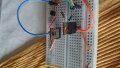
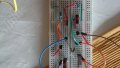
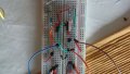
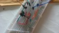
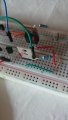
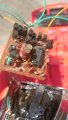
That's definitely not the problem.I've connected the circuit as you said but there are no voltages at any transistor , I think that 50 k to the base of BJT is too much?
I hate to say this, but how about an L293D?