Facebook
 Google
 GitHub
 Linkedin

I am working on a project in which ,
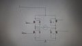
I have to build up a circuit (H-Bridge),with ECU as motor which draws(12V, 10Amps). Analog input to the H bridge done by Myrio (from NI) also to control and alternate switching of H bridge.Motor Cranking is main idea behind making this circuit. The circuit must be able to produce cranking pulse at start up A circuit with few passive components is what i am working on.
2 N-channel MOSFETS and
2-P channel MOSFETS. What other transistor do i need ?
Or a H bridge Driver IC.
The ECU (for eg) which is in place of motor draws some current (10Amps)
Everytime at start-up it is important to have this cranking pulses (test circuit to be made)
I have to build up a circuit (H-Bridge),with ECU as motor which draws(12V, 10Amps). Analog input to the H bridge done by Myrio (from NI) also to control and alternate switching of H bridge.Motor Cranking is main idea behind making this circuit. The circuit must be able to produce cranking pulse at start up A circuit with few passive components is what i am working on.
2 N-channel MOSFETS and
2-P channel MOSFETS. What other transistor do i need ?
Or a H bridge Driver IC.
The ECU (for eg) which is in place of motor draws some current (10Amps)
Everytime at start-up it is important to have this cranking pulses (test circuit to be made)
Attachments
-
 173.5 KB Views: 4