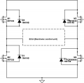
H bridge circuit with ECU (with control from Myrio)

Thread Starter

Bhargav Jani

Joined May 20, 2016
114
I am working on a project in which ,
I have to build up a circuit (H-Bridge),with ECU as motor which draws(12V, 10Amps). Analog input to the H bridge done by Myrio (from NI) also to control and alternate switching of H bridge.Motor Cranking is main idea behind making this circuit. The circuit must be able to produce cranking pulses.(Volatge level 12V to 7V) at start up and not below that. A circuit with few passive components is what i am working on. 2 N-channel MOSFETS and 2-P channel MOSFETS. What other transistor do i need ? Or a H bridge Driver IC.
 

Attachments

Last edited:

cmartinez

Joined Jan 17, 2007
8,758
I am working on a project in which ,
I have to build up a circuit (H-Bridge),with ECU as motor which draws(12V, 10Amps). Analog input to the H bridge done by Myrio (from NI) also to control and alternate switching of H bridge.Motor Cranking is main idea behind making this circuit. The circuit must be able to produce cranking pulses.(Volatge level 12V to 7V) at start up and not below that. A circuit with few passive components is what i am working on. 2 N-channel MOSFETS and 2-P channel MOSFETS. What other transistor do i need ? Or a H bridge Driver IC.
For starts, the 1N4148 diode is too small to handle the sort of kickback you'd be getting from a 10 amp load. I'd suggest you use a 1N4007 instead. Also, your diagram shows only n-mosfets, and not p-types.

The IRF530 might do the job, but I'd say it's pushing it, because it can handle only 14 Amps of continuous current. For an inductive load such as this, I'd suggest you use a mosfet capable of handling at least 3 times the motor's current.

My suggestion would be for you to use n type mosfets for all four transistors, and a ir2101 driver. This thread would be a good place to start studying this sort of circuit.
 

Thread Starter

Bhargav Jani

Joined May 20, 2016
114
I took a oscilloscope to a tractor yesterday and as I turned ON the starter I could see sudden drop in voltages upto 6-7V and so on within 200ms.


This behavior was recorded accordingly in the oscilloscope. The H bridge in the above schematic with Myrio (From NI) ,together have to attain this scenario of cranking once the FET\MOSFET has inputs from Myrio

Similarlly I have to make a LabView code and also GUI for the same..

But at first what components and the circuit design in eagle is important for me. I need to simulate the circuit before proceeding for PCB.

The aim is to have this cranking motor or such output waveforms at the Myrio GUI ,to see the behavior of this Circuit.

I shall go through your link once (as I too have to work with Ltspice for simulation)
 

Thread Starter

Bhargav Jani

Joined May 20, 2016
114
Can I use two IR2101 on both the sides of the H bridge. ?


Can Analog signals directly given to this IR2101 from a micro-controller ?
 

cmartinez

Joined Jan 17, 2007
8,758
Can I use two IR2101 on both the sides of the H bridge. ?
Yes, as a matter of fact, you have to.

Can Analog signals directly given to this IR2101 from a micro-controller ?
Not sure what you mean. If you want to control the speed of the motor, you will have to pwm (pulse width modulate) the inputs of the ir2101. Which is something that most micro-controllers can do.
 

Thread Starter

Bhargav Jani

Joined May 20, 2016
114
The load which I need to place is ECU (Electronic control unit ) of a vehicle

The aim of the circuit is to generate 'Cranking Pulses' Motor Cranking


But that is a secondary stage , firstly I need to use a load which will draw from (0-5amps) of current. In your thread, does any component value selection of IR2101 or N-channel Mosfet depend on this load value....

This load has to have voltage across it (dropped down to 7-8V ideally at the start up of a motor ) --Cranking scenario , which I wish to generate or control through this 4 N-channel MOSFETS

Did I make it clear ? .....
 

Thread Starter

Bhargav Jani

Joined May 20, 2016
114
Had a chat with a colleague, keeping aside the idea of ECU here

Firstly I will have to use a small resistor (in place of the motor) dropping resistor for instance.

The supply to the circuit will be 15V, The voltage and current across the resistor 12V with 5amps current drawn to be

I am confused here with the start voltage , needed voltage and the current drawn
 
Top