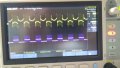
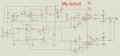
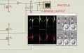
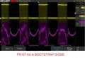
I would like to share oscilloscope photos. I almost obtained the same signal as proteus provided. But, when I increase the bus voltage, the spikes on the lower cycle gets huge and ruins the circuit. Ir2110 burnt couple of times. I actually take the project from an american university, I would like to improve it and use for my final project at university but i am having problems recently. I also share the orginal circuit down below. The biggest difference in mine is that bootstrap diode. In original circuit, ultra fast rectifier diode was used. I used schottky diode instead. Does it make too much difference? I don't have ultra fast diodes. Thats the reason why I used schottky.
It switches the mosfets. i can see filtered signal as well but when i go above 6 volts, my power supply makes a humming noise like a short circuit and lower cycle is totally distorted.
You do know your first schematic doesn't match the second one you posted don't you? If you are working with the first one in your experiment, Why does the lower half bridge connect to the other side of the inductor through C3? It is bypassing the inductor taking it out of the circuit when the bottom bridge is turned on. Is it possible that is the problem??
How are you connecting your scope? Are you using a differential probe to measure accross you output load? You cannot connect the scope ground directly to the output or the earth of the scope will short the inverter output. Thats what you were doing in proteus also, it looks to me like you've shorted one of the phases.
How are you connecting your scope? Are you using a differential probe to measure accross you output load? You cannot connect the scope ground directly to the output or the earth of the scope will short the inverter output. Thats what you were doing in proteus also, it looks to me like you've shorted one of the phases.
It switches the mosfets. i can see filtered signal as well but when i go above 6 volts, my power supply makes a humming noise like a short circuit and lower cycle is totally distorted.
[/QUOTE]
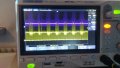
Whats your purple trace? it looks like you have some sort of PWM on there? The noise seems to be cause by the switching thats going on on that purple trace. Remove your inductor and capacitor filter and see if the envelope of your sine goes as expected. It will be noisy but the shape should be correct, you'll still need a load connected. I suspect what your seeing is the back emf of the inductor.
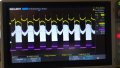
The purple one is the pwm from h-bridge. It represent the blue signal on proteus(please see the proteus photo). Just removed the inductor. I still have the same problem. When I increase the voltage, it makes a humming noise and seems to be a short circuit.
The purple one is the pwm from h-bridge. It represent the blue signal on proteus(please see the proteus photo). Just removed the inductor. I still have the same problem. When I increase the voltage, it makes a humming noise and seems to be a short circuit.
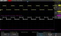
Can you zoom in there appears to be a lot of high frequency fuzz there so you need to zoom in on perhaps one or two cycles to see whats going on. The filter needs to be the last thing you add once you know everything else is right. One thing i notice on your white trace is that for some reason your always going past the zero crossing point (the dead time between cycles) within a cycle. it should be positive for one half cycle and negative for the other. I also note its not symetrical around your dead areas which also wouldn't be correct to generate a sine wave.
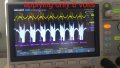
I figured out that my power supply makes the humming noise. When it reaches to certain voltages levels, it triggers some relays. And it ruins my circuit. So, instead of increasing voltage while the circuit is still running, I started with a fixed voltage level which seems to solve the problem. But i still have this high frequency spikes. It's annoying. I attached photos with the zoom in..
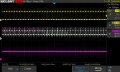
the little spikes on the rising and falling edges look to be due to stray inductance in your circuit, wires and long tracks etc and are probably not a major issue at the moment. Of more concern is the zero crossing point which looks to be giving some dead and instability in your one half cycle but no dead time on the other potentially getting some shoot through. You need to focus of timing of your 4 control lines around the zero crossing point to see if theres any overlap.if there is you will need to improve your bridge driver circuits to remove offsets etc. Everything strange going on can be seen on your yellow trace so you should be able to focus on that without the power stage powered and save yourself some repairs and money
I just applied 25 volts. Never reached that before. If I could remove the spikes, I would probably see the sine wave. I removed one of the IR2110 which controls the 50khz frequency spwm. All the spikes on pwm signal dissappeared.
I just applied 25 volts. Never reached that before. If I could remove the spikes, I would probably see the sine wave. I removed one of the IR2110 which controls the 50khz frequency spwm. All the spikes on pwm signal dissappeared.
If you removed the IR2110 then you've removed the driving of the H bridge. Thats perfect.
If you can measure all four control lines at the same time with a scope and check there is no overlap with the digital control lines for the IR2110 specifically around the edges.
Once you've confirmed thats all right only then start adding the power stages.
 Facebook
 Google
 GitHub
 Linkedin
 2.9 MB Views: 58