The 'working' version is always providing a positive voltage as drawn as its referenced to GND so isn't operating as an H bridge. Its just controlling the half cycles of the sine wave.
An H Bridge provides positive and negative voltage to a load by reversing its polarity which is what you were looking at prior to jumping back to this.
I'm pretty much convinced what you have is working, a bit of damping to eliminate the fuzz on the edges and your there. Could you post your proteus file i've just got the demo to see if i can advise on the scope
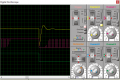
It works. See attachment. I changed your scope lines and filter values and deleted your ground on the output. Nice Sine wave Unfortunately can't save it as its a demo. Screenshot below
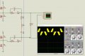
They are caused by whats call the zero crossing point where both sets of switches are technically 'off' so you get a voltage spike caused by the inductance in the circuit and capacitance of the mosfets. In terms of reality yes they can be significant (EMI being one) but it depends how far you plan on taking this circuit. A RC snubber (RC accross mosfets) or TVS Diode could be used to clamp the spike and bring these voltage levels down and disipate the energy there instead.
Before you go looking at that i'd focus on getting the simulation more real first. What i mean by that is Currently the inductors and capacitors in the filter are 'ideal' so isn't truely representative, try the filter in my earlier post with some parasitic elements added which would be more 'realistic' then find some real parts of the rating you need and put in the values off the datasheet it can make a big difference.
You also have some clipping of the Sine at the top which will effect your harmonic distortion but again its only an issue if you want a 'pure' sine.
Well done on getting as far as you have. Inverters can be tricky things to get right. Hopefully a couple of things i've pointed out to you will make sense.
If you do plan on making this as a real circuit provision for the solutions now, its easier to remove parts off a PCB than bodge them on later.
I ordered PCB from China. I will check whether it works in real. I would like to ask a dump question by the way. Can I use h-bridge driver( ir2184) instead of high low side driver(ir2110)? If I can't, why? Last but not least, if I use tl084 for triangular wave generation, what's maximum frequency value I can get?
I ordered PCB from China. I will check whether it works in real. I would like to ask a dump question by the way. Can I use h-bridge driver( ir2184) instead of high low side driver(ir2110)? If I can't, why? Last but not least, if I use tl084 for triangular wave generation, what's maximum frequency value I can get?
Yes, its an HBridge Driver so will have the same functionality.
The TL084 has a slew rate of 14V/us so the max speed will be dictated by this.
If you have a 5V Ramp which is symetrical rise and fall, The time for the output to go 5V from 0 will be appox 357ns, as it also has to return to 0V then this would double the time to 714ns which equates to approx 1.4Mhz. If your reference has smaller ramp the frequency could increase slightly. One thing to note though is at those frequencies you'd need to look at your power stage, including the FET drivers to determine the max frequency of those as i suspect this will be more of an issue.
Yes its the zero crossing point, the point which it goes from positive to negative in the cycle. The inductor in your case creates a back EMF as is resisting the instant reversing of the current of the inductor.
Try putting diodes accross the Drain Source of your Mosfets and see if it changes anything. Maybe your mosfet model doesn't contain them internally
If that has no impact then you could look at using a snubber accross the switches to damp some of the energy but before doing this start by creating a more realistic model for a real inductor and capacitor as they have (resistance) losses not currently present in your circuit which should damp some of the spike. There's no point addressing the snubbers unless you have the charateristic for the components in there first.
I couldn't make snubbers and the diodes work on proteus as i intended to. But, I would like to order tvs diodes instead of making snubbers when i make the circuit in real. How can I select a proper tvs diodes for my case? Should it be connected parallel to mosfets?
 Facebook
 Google
 GitHub
 Linkedin