Creating Band Pass filter in Proteus

Thread Starter

deepakdpadhi

Joined Sep 29, 2018
19
Hey guys,
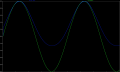
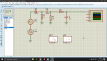
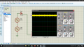
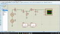
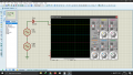
I've been trying to create an AM modulator on proteus. So I managed to reproduce the circuit using a laplacian filter block (as given in the diagrams). But when I replace the Laplacian blocks with their RC counterparts, I don't get the modulated signal.
Additional details:
Vc is 1MHz. Vm is 1KHz.
R1=3300 C1=33pF
R2=470 C2=470PF

T for HP1 =R1xC1 =220.9ns
T for LP1 =R2xC2 =108.9ns

As shown in the images attached, the circuit works with the Laplacian filter blocks but not the RC filter. What am I doing wrong?
 

Attachments

Bordodynov

Joined May 20, 2015
3,179
Load the diode cathode with a resistor. For example, take a 1 kOhm resistor. When using RC, the Input capacitor is charged and closes the diode. But I'll tell you what I think - it's a bad modulator!
 

Thread Starter

deepakdpadhi

Joined Sep 29, 2018
19
Load the diode cathode with a resistor. For example, take a 1 kOhm resistor. When using RC, the Input capacitor is charged and closes the diode. But I'll tell you what I think - it's a bad modulator!
I tried adding the resistor. But the output was the same (0). Any other ideas?Screenshot (24).png
 

Bordodynov

Joined May 20, 2015
3,179
You don't understand me. I did not offer a serial connection. I offered to load the diode with a resistor. One pin of the resistor to the cathode and the other pin to the ground.
 

Zeeus

Joined Apr 17, 2019
616
See where the 1k is..Think that's what Bordodynov means...
green waveform is 1khz input and blue is output : see distortion at bottom of output signal? Please you can explain why?

And the output signal is smaller

For higher output think best to do envelope detection : load output of diode with capacitor and not resistor then use charging and discharging time

Not sure

finally : is this how to get AM signal? carrier + 1khz?
 

Attachments

Thread Starter

deepakdpadhi

Joined Sep 29, 2018
19
See where the 1k is..Think that's what Bordodynov means...
green waveform is 1khz input and blue is output : see distortion at bottom of output signal? Please you can explain why?

And the output signal is smaller

For higher output think best to do envelope detection : load output of diode with capacitor and not resistor then use charging and discharging time

Not sure

finally : is this how to get AM signal? carrier + 1khz?
I'm trying to replicate the switching modulator given in these posts :
https://www.tutorialspoint.com/analog_communication/analog_communication_am_modulators.htmhttps://electronicspost.com/explain...square-law-modulator-and-switching-modulator/
 

Thread Starter

deepakdpadhi

Joined Sep 29, 2018
19
You don't understand me. I did not offer a serial connection. I offered to load the diode with a resistor. One pin of the resistor to the cathode and the other pin to the ground.
Thanks for replying again. I used a pull down resistor as you suggested, but it gives a completely different waveform, and not the one I want (as given by the Laplacian filter in my question).
 

Attachments

Thread Starter

deepakdpadhi

Joined Sep 29, 2018
19
oh not demodulator..Thanks for link

Getting like you at first but one way to get what you want is to add dc voltage in series with the 2 sources

and she said use lc bandpass filter though : your Rc values for cutoff..shouldn't it be 999khz and 1001 khz?
We have a set of resistors we are allowed to use in this circuit, and nothing more, so this was the closest I came. Anyways, adding DC worked and now I can see the modulated signal.
Thanks guys,.
 
Top