Facebook
 Google
 GitHub
 Linkedin
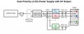
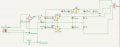
I'm working on creating a PSU which is to supply +/-15v and 5v on one board and +/-12v and +/-6v on another board. The problem is that it keeps blowing my 3 amp slow blow fuse. I'm pretty new to all this and realise I'm stuck. Obviously maybe up the fuse. However, it's not supposed to be creating a load ( I don't think)  .
.
.
Last edited by a moderator:


")