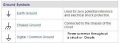
1a Correct but often misused as an all encompasing power common as well as Earth Ground.
See section 1 & 111 for the comments on incorrect usage. Ground Practices
Max.
1a Correct but often misused as an all encompasing power common as well as Earth Ground.
See section 1 & 111 for the comments on incorrect usage. Ground Practices
Max.
I am one who has consistently misused it, but am going to do better in the future. As I use 1c, should it be labeled Com or something else or left unlabeled?
Usually left unlabled unless more than one commons that are not connected to each other.
I tend to use the term COM or Common as the often used term Ground is also used for a earth ground in N.A. This can lead to even more confusion.
Max.
The main problem is if standards are disregarded, then the whole purpose of setting a standard is for naught.
BTW, the symbols shown were defined back in the early '50'2. One standard set by the JIC which then became NFPA79.
Max.
I found it odd that the Art Of Electronics, often used by those as a learning tool, (mis)uses the symbol all the way through the book.
Also I do not recall ever seeing a list of symbols and their usage in schematic drawings etc in the book.
Max.
I found it odd that the Art Of Electronics, often used by those as a learning tool, (mis)uses the symbol all the way through the book.
Also I do not recall ever seeing a list of symbols and their usage in schematic drawings etc in the book.
Max.
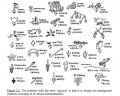
I concur with the OP Fig. 1. Unlike a return, grounds distinguish themselves by not having current flowing into or through them under normal operating conditions.
According to some, it appears TI and Horowitz and Hill use the wrong symbol for "ground." Here is just one of tens of thousands of examples from TI (Source: TI Handbook on Op-Amps):
We also have EAGLE (cadsoftuse.com) supposedly misusing the earth ground symbol (Source: Eagle 7.5.0 Supply1 library):
And this is what our friends at Sparkfun have to say:
Allowing for the slight difference in the number of horizontal bars in some symbols (Is that really important?), is anyone for one second confused by such claimed misuse (See: posts 12 &13) ) of what they consider is the symbol for Earth ground* and only Earth ground? Can one not argue that H&H and TI are perfectly right in using the symbol for Earth ground, since it will always suffice in the context of what is written? Whereas, if another symbol were used, it might not be appropriate in all circumstances? Frankly, I loose more sleep over whether my shoelaces need ironing. :-J
Of course, this comment is not meant to imply there are not important differences. Such differences are best done by appropriate labeling, either by words or legend on the schematic, rather than by trying to untangle the uses and misuses over the past many years.
John
* Or, is earth ground mistakenly meant? A bucket or earth sitting on a glass plate is not Earth ground.
The only thing I am trying to untangle is my understanding of the symbols. As many of you know, I have no formal training in electronics; what I know, I have learned through reading books, magazines, and the internet and via experimentation. I have drawn many schematics and published a fair number of them, and most (if not all) have used what is apparently the wrong symbol. I don't intend to go back and correct the mistakes of the past, but I don't want those mistakes to keep me from using the correct symbol in the future. And although I have never actually ironed my shoelaces, I have been known to take them out of my sneakers, wash them, and press them out flat to dry.
One issue is it can cause a problem where I have seen a circuit drawn with AC supply L1, N & Gnd. feeding a isolation transformer and then the DC common also has a earth gnd symbol, and the common is not intended to be connected to earth ground.
It amuses me that everyone has no problem using a notation on Every power supply point, 5vdc, 12vdc, 24vac etc, but for the commons we are often left to guess.
BTW, Kicad has the whole range of supply common symbols, probabally being European and now Cern has a influence in it.! @tracecom what I would suggest is stick to the standard symbols and use good practice from the beginning.
BTW, I can cite a few manufacturers sites that include a certain engineering definition that is totally wrong, just because they do this does not make it right, also those that use this as a learning tool also pick up the wrong definition.
Max.
I've always considered 1A to be a hard ground - meaning zero volts. 1B is a chassis ground, which may also be zero volts but is isolated from absolute ground - which is what the mains ground is considered to be. This can be useful in radio equipment where an antenna may have a radial and a ground plane which the signal can bounce off of. 1C is what I consider as a "Common ground point, meaning it's a common point whose voltage doesn't necessarily act as a zero point. It could be (in my understanding - someone will correct me if I'm wrong) but it could be a voltage that is not equal to zero volts. It could be 5 volts. Hell, it could be 50 volts or even 5000 volts. As long as it is common to the entire circuit it's considered ground.
You can't absolutely rely on there being any hard and fast rule that everyone adheres to, but the one on the left with diminishing horizontal lines is often associated with the safety earth that comes from the wall outlet. The middle one with slanting lines usually means chassis, these days its more of a throwback to when there was an actual metal chassis that all the components were mounted on. The hollow tri-angle one on the right should come with a safety warning - its most often used on the negative side of a direct off mains bridge rectifier and is pulsating at the peak negative value of the AC mains. In most cases; the rectifier is followed by the PWM circuit, and the point indicated by this symbol is the most negative and the 'ground' reference for any measurements - but its not ground, its not earth and it is dangerous!
 Facebook
 Google
 GitHub
 Linkedin

")