Facebook
 Google
 GitHub
 Linkedin
Goodmorning,
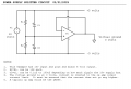
I'm a civil engineering using LTsplice for my thesis. I want to try for my circuit configuration to use only one battery and i have to use an amplificator which need positive and negative current.
I've tried a lot of different configuration, some found online, some invented by me but it doesn't work; I need to generate a positive and a negative continuous current from a single current if possible.
is it possible? how should i do it?
(I already tried the configuration below, the only one that work is V5 V6 but has 2 battery, V4 create 2 current but aren't continuous so the amplificator doesn't work (I think it's because of this))