This appears to be LTSPICE. You can set the voltage values of 1 and 0. I have set the 1 value to 3.3V or 5.0V or 12V I have not tried setting the 0 value to -4V.
There are good helps for LTSPICE.
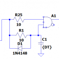
It appears that you are trying to construct a circuit that has a very specific behavior, but doing so by tweaking simulation parameters to get the models to produce the results in the computer that you want. But if you want to then construct a physical circuit that behaves the way you want, you need to do it the other way around. Get the models tweaked so that the simulation results match their actual behaviors and then construct a circuit that, using those reality-based models, does what you need. At that point, you have a fighting chance that the physical circuit will be reasonable close to the simulation results.
 Facebook
 Google
 GitHub
 Linkedin
 6.7 KB Views: 8


