Full bridge inverter with charger

Ian0

Joined Aug 7, 2020
13,158
Another point is which regulations it has to pass:
A UK Spec emergency lighting unit has to be able to run off its batteries for 3 hours and charge back up again in 12 hours. So its charger has to be rated about 25% of the inverter,
A continental Europe spec emergency lighting unit has to run off batteries for 1 hours and charge back up within 12 hours. So its charge rating is about 8% of the inverter.
Some UPS units have only to power the load for a few minutes whilst whatever it is protecting shuts down properly, and probably can take 12 hours to recharge. So the charger rating is even less.
For chargers rated <10% of the inverter rating, it may well be cheaper to produce a complete charger separate from the inverter rather than involve the extra complexity.
 

MisterBill2

Joined Jan 23, 2018
27,741
There is also, hopefully, adequate control to avoid overcharging and damaging the battery or battery pack. The number of UPS systems discarded after just two or three years because the batteries will no longer power the load for even a quick shutdown, when the total backup time during those years is less than an hour, tells me that the charge system is doing something wrong to the batteries. Evidently the recovery charge or the float charge current are excessive.
 

Ian0

Joined Aug 7, 2020
13,158
There is also, hopefully, adequate control to avoid overcharging and damaging the battery or battery pack. The number of UPS systems discarded after just two or three years because the batteries will no longer power the load for even a quick shutdown, when the total backup time during those years is less than an hour, tells me that the charge system is doing something wrong to the batteries. Evidently the recovery charge or the float charge current are excessive.
Stricter standards apply for emergency lighting (people's lives depend on it) than for UPS. The requirements are for 10-year life guaranteed batteries, temperature compensated float voltage, deep discharge protection etc.
 

Thread Starter

Joeadeoye

Joined Apr 2, 2017
49
Stricter standards apply for emergency lighting (people's lives depend on it) than for UPS. The requirements are for 10-year life guaranteed batteries, temperature compensated float voltage, deep discharge protection etc.
OK, @lan0 I have been in the lab performing experiments based on the circuit you posted using leakage inductance L4 and I have noticed alot of things. Though I fried some components but it's part of the job. So here are my observations.

I started by arranging the full bridge using 2 mosfets and 2 diodes, I replaced both high side mosfets with diodes cos I noticed either switching them or not, current will always pass through their body diodes, so, I simply replaced them with diodes to make things easier, and also won't be needing bootstrap circuit for switching high side mosfets, so I'm left with the two low side mosfets and diodes sitting on top of them

Next, I connect thr 7v transformer to the drain pin of the mosfets and a capacitor at the output and then I powered the transformer, and measured the output voltage, I measured 4v instead of 7v (I assumed it's due to diode loss, cos I haven't done anything complicated yet)

Now, I used Cd4047 IC to create pulse at 100Hz and put at the gates of the mosfets and powered the circuit... I heard some horrible notice in the transformer and I saw some smoke on my breadboard..

Now, I did some maths, since the mains frequency is 50Hz and I want each pulse on the mosfet on every half time of each half cycle, since a half cycle is 10ms, so I want to switch on at 5ms in each half cycle, so I ended up with creating a other pulse at 50Hz but 12.5% duty cycle. I powered the circuit and, the transformer was making some clugging sound, mosfet gets hot quickly, although didn't blow up, and voltage increased by just 0.5v so I have 4.5v.

I try to adjust the duty cycle gradually, and the voltage increases as I increase the duty cycle, but ends up sinking more current which melt my jumper wires, so I took a different approach.

I noticed as duty cycle increases, it gives more time for current to flow and charge the leakage inductance of the transformer, but in turn, generating too much heat. Now I decided to bump up the frequency to 300Hz and I noticed a huge difference.
First, the notice reduced in the transformer, the current sinking reduced, voltage increased a little.

Now I decided to connect a load, so to be sure I'm getting real voltage and not just floating voltage that will drop immediately load is connected. I used a 12V 20watt bulb and measure again, voltage didn't drop.

I keep increasing the frequency gradually till I got to 500KHz (I changed to 555 timer) and I was able to boost from 4v to 10v (with load connected). I have used the lowest capacitor I have 101 (100pF). I believe if I am still able to switch faster, I can still boost the voltage more, with sinking little current and mosfets only get warm (not hot).

This method is a boost converter method, although similar to the boost PFC which was suggested by lan0 in previous comments, just the difference is the mosfets switching methods as PFC controller is a bit complicated to understand.

In summary, using the leakage inductance of the transformer, I was able to boost the voltage from 4v to 10v DC with just 100uF output capacitor and 20watt load connected. I will order the 3525 IC and try switching at more higher frequency if I'll be able to attain 13.8v needed to charge the battery.
 

Ian0

Joined Aug 7, 2020
13,158
The boost PWM frequency would be the same as the inverter PWM frequency.
Have you measured the leakage inductance of your transformer? Was it designed to have significant leakage inductance?
 

MisterBill2

Joined Jan 23, 2018
27,741
It would be simpler, but probably not cheaper, to simply use a buck converter for the battery charging function..

But now I ask: Is this a product design? or just a "one-off" for some project, or personal use?? If not a product design then certainly a buck supply for charging is the way to go because then neither mode needs to compromise a single bit. THAT can be a great benefit.
 

Thread Starter

Joeadeoye

Joined Apr 2, 2017
49
The boost PWM frequency would be the same as the inverter PWM frequency.
Have you measured the leakage inductance of your transformer? Was it designed to have significant leakage inductance?
I don't have LCR meter to measure the leakage inductance. You said "the boost PWM frequency would be the same as inverter PWM frequency". The inverter frequency is 50Hz, the mains AC frequency for charging is also 50Hz, so are you saying the boost PWM frequency should also be 50Hz? And what duty cycle will that be?
 

Ian0

Joined Aug 7, 2020
13,158
I don't have LCR meter to measure the leakage inductance. You said "the boost PWM frequency would be the same as inverter PWM frequency". The inverter frequency is 50Hz, the mains AC frequency for charging is also 50Hz, so are you saying the boost PWM frequency should also be 50Hz? And what duty cycle will that be?
No - 50Hz is the line frequency - the PWM frequency will be between 16kHz and 100kHz depending on the design. If your transformer is toroidal, and not designed for leakage inductance, then the leakage inductance is likely to be too small.
Post #26 shows a transformer designed for a specific leakage inductance.
An EI laminated transformer with a two-section bobbin will have enough leakage inductance. One that is concentrically wound won't.
 

Thread Starter

Joeadeoye

Joined Apr 2, 2017
49
It would be simpler, but probably not cheaper, to simply use a buck converter for the battery charging function..

But now I ask: Is this a product design? or just a "one-off" for some project, or personal use?? If not a product design then certainly a buck supply for charging is the way to go because then neither mode needs to compromise a single bit. THAT can be a great benefit.
Thank you so much for that, I have also thought about the buck converter option and i have designed one already and it worked. But, I am just curious how these commercial inverter UPS does the magic.

If you open up an inverter UPS, you see that the mosfets are arranged in full bridge configuration, the battery + wire is always tied to the high side mosfet heat sinc (since both high side mosfets share same heat sinc) and the transformer is always connected to the low side mosfet's heat sinc. Then the battery - wire is mostly tied to the source pin of the low side mosfets.

Looking at this configuration, you can tell that the AC coming from the transformer (when it is in charging mode) goes to the drain/source pin of the low/high side mosfets respectively (which is the same thing in the circuit that lan0 posted previously) and looking at where the battery + and - wire are located, you can easily tell that those mosfets body diodes form bridge rectifier to convert the incoming AC to DC and straight to the battery.

Now I know the magic lies in the switching of those mosfets, how they are being switched, the duty cycle they are being switched, the frequency they are being switched, and their mode of switching, which will then bring the output voltage up to the voltage required to charge the battery.

I am pretty sure the ups transformer would have been designed to have some leakage inductance because the battery + wire is just tied to the drain pin of the high side mosfets directly, if not, the battery + wire would have been somewhere else on the board.

I don't currently have a working commercial inverter ups, I would have opened it up and use oscilloscope to study how the mosfets are switching in charging mode.
 

Thread Starter

Joeadeoye

Joined Apr 2, 2017
49
No - 50Hz is the line frequency - the PWM frequency will be between 16kHz and 100kHz depending on the design. If your transformer is toroidal, and not designed for leakage inductance, then the leakage inductance is likely to be too small.
Post #26 shows a transformer designed for a specific leakage inductance.
An EI laminated transformer with a two-section bobbin will have enough leakage inductance. One that is concentrically wound won't.
The transformer is EI laminated transformer
 

Ian0

Joined Aug 7, 2020
13,158
Victron uses separate inductors in some of its products. It might be to reduce core losses: I'm not quite sure how one would calculate the core loss of leakage inductance - after all it is caused by magnetic flux that doesn't go through the core. Obviously a 50Hz transformer, either EI or toroid, has laminations suitable for 50Hz which would make eddy-current losses at 20kHz, but how much of the 20kHz flux goes through the core?
 

Thread Starter

Joeadeoye

Joined Apr 2, 2017
49
OK, so I was able to lay my hands on a commercial inverter UPS, it's a 48v system and I'm sure it will be the same method used as in 12v system.

So I took it to the lab and rip it open. I took my oscilloscope and start taking readings and figured out alot of things. I'll share my discovery soon
 

MisterBill2

Joined Jan 23, 2018
27,741
G
I do not recall ever seeing a UPS iven that usually what failes on the UPS used with a computer is the battery pack, because it fails after only a very few years and probably not even an hour of actual backing up, is it a reasonable guess that battery life is not one of the primary design goals?? Most designs are done to optimize some parameter, in the UPS it seems to be mostly backup power wattage capability, followed by actual backup time at full load.
I do not recall ever seeing a UPS touted for the long life of the battery pack, so probably that is not top of the list.
Meaning that probably battery charging is not optimal.
 

Thread Starter

Joeadeoye

Joined Apr 2, 2017
49
I opened up the inverter and first, I saw the heat sinc was arranged in full bridge configuration, I was glad to see that. So, I checked the voltage on the battery (with inverter connected) it was 48.6v, now I connected the inverter to mains power for it to begin charging, and I measured again, and got 51.3v which indicate it is charging. Now I grab my oscilloscope and start taking readings.

First, I checked the AC voltage on the transformer, it was 27v AC, which is what I was expecting. I used my scope to check the gates of each mosfet in the bridge, and saw they were all switching at 20KHz but at different duty cycle.

High side A and high side B is switching at 60% duty cycle. Low side A and low side B is switching at 40% duty cycle.

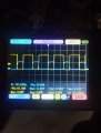
Now, I checked low side A and low side B simultaneously on both channels of the oscilloscope, and I saw that they were switching at the same time from same signal at 40% duty cycle, same time ON and same time OFF and same duty cycle.
IMG_20240617_174107.jpg
I also checked high side A and high side B simultaneously, and they were also switching with same signal, same time ON same time OFF and 60% duty cycle.

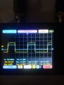
So, I checked high side A and low side A simultaneously, and they were 60% and 40% duty cycle respectively, switching alternatively, i.e, when high is ON low is OFF, and when low is ON, high is OFF
IMG_20240617_180205.jpg
The yellow channel is high side and blue channel is low side.

I also noticed that, immediately I connect it to the mains, the duty cycle starts at 10% and gradually increases also with the voltage, till it gets to 40% duty cycle (at the lower side)
 

Thread Starter

Joeadeoye

Joined Apr 2, 2017
49
I was also able to lay my hands on a 12v inverter UPS, when I opened it, the transformer was 7v-220v, which is exactly the same as I have. I also used my scope to check the switching while charging and it was similar to the 48v inverter, just that the duty cycle is 50%, the frequency is same 20KHz
 

Thread Starter

Joeadeoye

Joined Apr 2, 2017
49
After seeing all these, I went back to my breadboard, I setup a 20KHz PWM using 555 timer, took my transformer and connected the 7v side to my mosfet bridge, I connected the 220v side to mains AC, without switching, I got 4v DC from mosfet bridge, I powered the breadboard and start switching, at first, no voltage increase, so, I started increasing the duty cycle starting from 10% till I got to 50%, and the voltage gradually increased from 4v to 5v, which is not what I was expecting.

I tried everything I could, I couldn't get pass 5v DC, i bumped up the frequency, still no difference, so I decided to change the output capacitor from 35v 100uF to 35v 1000uF, and I was able to get to 5.5v.

Then I changed it again to 16v 3300uF and I was able to get to 6.3v, so I added 3 of the 3300uF capacitors in parallel, but no difference. So, my best result was 6.3v

I don't know what is happening or what I am doing wrong.
 
Top