Facebook
 Google
 GitHub
 Linkedin
Hello, I've been having difficulty dealting with circuit analysis.
Here, for example, I'm given the task to find the voltage on Vs. But I fail short half-way through.
Also, I don't understand how to deal with negative voltages and/or currents, and would appreciate help!

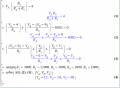
My attempt at solving this:
V(R5)=4 V because parallel to that thing
I(R4)=4V/1k=4mA=I(R3)
2k=V(R4)/4mA => V(R4)=2k*4m=8 V
Then I applied mesh equation to last mesh:
V(IA)+8V+4V=0 <=> V(IA)=-12 V (How?)
Node equation at a:
2mA=4mA+I(R3) => I(R3)=-2mA (What does this mean?)
V(R3)=3k*(-2mA)=-6 V
Mesh on middle:
-12V-(-6V)-(-6V)+V(R2)=0
V(R2)=0 Impossible
Please help me understand what I did wrong, and consider as if I was very dumb (which is probably true).
Here, for example, I'm given the task to find the voltage on Vs. But I fail short half-way through.
Also, I don't understand how to deal with negative voltages and/or currents, and would appreciate help!
My attempt at solving this:
V(R5)=4 V because parallel to that thing
I(R4)=4V/1k=4mA=I(R3)
2k=V(R4)/4mA => V(R4)=2k*4m=8 V
Then I applied mesh equation to last mesh:
V(IA)+8V+4V=0 <=> V(IA)=-12 V (How?)
Node equation at a:
2mA=4mA+I(R3) => I(R3)=-2mA (What does this mean?)
V(R3)=3k*(-2mA)=-6 V
Mesh on middle:
-12V-(-6V)-(-6V)+V(R2)=0
V(R2)=0 Impossible
Please help me understand what I did wrong, and consider as if I was very dumb (which is probably true).
Last edited: