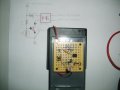
Here is a photo of the wired up board. The only thing I am not sure of is the sequence of the leads on the transistor. The back of the package labeled the center post as the base, the bottom as the emitter and the top as the collector. I wired the E to the ground, the B to the 1K ohm resitor, and the C to the 2 pin of the optocoupler. I got this diagram from radio shacks data page. Any help?
I wired this according to the diagram on page 3, post 24 (I think). There is a power supply to the optocoupler and to the photocell and transistor. The e of the transistor goes to ground and the B goes to voltage. The C goes to the 2 pin of OC
Pin 4 is the emitter. You can connect it to ground. Pin 3 is the collector. You can connect the collector to your positive power rail using a 4.7K resistor. Then you can use a DVM to measure the voltage across pin3 and pin4 of the opto-coupler. Use your meter set to voltage.
Block the light to the LDR an the voltage on the DVM should be less than 100 millivolts. Shine a light on the LDR and the voltage should jump to very close to your positive power supply voltage.
What is pin 4? Do you mean the Optocoupler (OC) pins? All I need to do is close a switch with no voltage output (ground two leads) on the output of the OC. I need a schematic to follow, I am not an electronics expert by any means. I am not sure of the placement of the pins on the OC either, it was suggested that the pins are numbered counter-clockwise from #1. So I don't know if my transistor is wired correctly and I am not sure of the OC. The resistors are wired according to schematic on page 24, BMorse wired one up and made it work according to the needs of my timer. Thanks jon
First, compare my attachment in post #37 to see if the opto-pins are correct.
Then, an easy way to see if the main circuit is working is this:
Put the positive (red) lead of your VOM, MM or whatever on the 330 resistor on the lead closest to the plus mark. Then, put the black probe on the resistor lead going to the opto-device. This is called measuring across the resistor. With the power on, shine a light on the sensor. You should see a corresponding drop in voltage. That is because current is flowing through the resistor. If current is flowing there, the circuit has to be working.
I have no voltage flowing from Pos on the up side of the 330 resistor to the downside of the res. (front of OC pin 1) When I measure across from pos (upside of 1k resistor) to downside, I have small voltage (.78v) and when I shine a light on Photocell that voltage jumps to 6v. What should I test next (I am still not sure about the transistor)
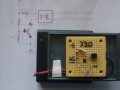
Hello barrelracer, sorry I was a little busy and haven't had time till now..... anyways as for your existing circuit the transistor is in backwards, the pin you have connected to the optocouplers pin2 should be connected to ground, and the pin connected to ground should go to the pin2 of the optocoupler, once you have this circuit connected to your counter module, the transistor will close those - and + pin connections on the counter, but to test it on the bench without the counter module, you will have to connect a 10K resistor to the pin 4 of the optocoupler, and connect pin 3 to ground. If you have your multimeter handy, set it to read DC voltage, connect the red lead in between the 10K resistor and pin 4, connect the black lead to ground, now once the circuit is powered, your meter should display 5 to 6 volts (if that is your power source) when the laser is pointing at the photocell, once the laser is blocked, the meter should drop down to nearly 0 volts....
so the 10K resistor is needed to test the circuit before you connect it to the counter, the counter module already has that on it so you won't need it once you are ready to connect your trigger circuit to the counter module...
that looks better, the transistor should work now.... now you just need a 10K resistor and wire it to the circuit the way I showed on the photo I edited... then you should be able to test the output to see if it toggles low when the laser beam is interrupted......
I will have to stop in town to get some 10K resistors,I am assembling the timer now(word of advice, DON"T touch the tip of a soldering Iron against the inside of your wrist, it makes a bad smell!!)
HI, I did get this to work, but I need a detector that is more sensitive to laser light than the photosensors. Would a phovoltaic cell work better? What is the detector screen in my construction laser detector? Any help?
HI, I did get this to work, but I need a detector that is more sensitive to laser light than the photosensors. Would a phovoltaic cell work better? What is the detector screen in my construction laser detector? Any help?
As I suspected, the green lasers wavelength would not be enough to trigger the CDS... I had tested my circuit with a red one....... maybe a photovoltaic cell could work, but then again, those would respond better to red lasers than green......
I will check my archives to see what I can come up with, I do have a circuit for measuring the output power of a laser, so maybe I could base a circuit off of that to make a Green Laser trigger........
does the green one have any affect on the circuit? maybe at a closer range? If so maybe the circuit can have some kind of amplifier circuit built in.....
BTW, here is a source for some good photovoltaic cells (Solar Cells) that could work for detecting the lasers output, pretty small and reasonably priced.... but like I said, green laser may not work as well as a red one.... >>http://www.solarbotics.com/products/scpd/
Really good to hear from you again, the green laser works really good at range if it is lined up just perfectly so the beam intersects one of the curves of the photo cell curcuit. (It also functions better if the PC is at an angle to the beam, rather than straight on) My detector for my construction laser looks like a PV cell, and it is very sensitive to laser light, would this be a better option? I have Red lasers too, there doesn't seem to be a difference in performance of the detector, but the green laser seems to project a much more powerful spot of LL than the red (big difference)
Yes for those detectors in the construction lasers is usually a photovoltaic cell (solar cell) I actually have a few of those I posted in the above link, I can devise a circuit utilizing one of those when I get home and I will post the circuit on here for you to try, it should not be hardly any different than what you have we will just have to replace the CDS with a PV..... BTW, do you have a small cheap calculator laying around with a solar cell across the top? If you do, you may be able to tear that apart to get the solar cell out of it to use as the sensor (carefully remove it if you can, these are fragile and can break easy!)......(quick way to acquire one in a pinch! )
Yes, unfortunately the cells only put out around .5 volts , and fragile
Speaking of .5 volts........ @ BarrelRacer :
I played around with one of those PV's tonight and it will definitely have to use some kind of amplifier for the PV's output, it is not strong enough to switch the transistor.....
and also, (Did not feel like skimming back through the whole thread... so sorry if you already posted this, it has been a while....) did you ever measure the resistance of the CDS you are using? what did it read with the laser on and off?
With my test circuit here, I can still trigger the circuit with a red (dollar store) laser pointer at nearly 60 feet .... my CDS reads around 150 ohms when the laser is on it, and over 2 mega ohms when the laser is off..... maybe we just need to find a "better" CDS for your circuit.....
 Facebook
 Google
 GitHub
 Linkedin
 What is pin 4? Do you mean the Optocoupler (OC) pins? All I need to do is close a switch with no voltage output (ground two leads) on the output of the OC. I need a schematic to follow, I am not an electronics expert by any means. I am not sure of the placement of the pins on the OC either, it was suggested that the pins are numbered counter-clockwise from #1. So I don't know if my transistor is wired correctly and I am not sure of the OC. The resistors are wired according to schematic on page 24, BMorse wired one up and made it work according to the needs of my timer. Thanks jon