Exhaust valve actuator

Status
Not open for further replies.

Thread Starter

BR1988

Joined Apr 14, 2021
51
Hi there,
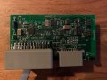
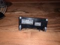
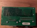
Sorry i took some time to reply, but I made some pictures of the bt controle module.

@les,
Yes I do have the BT controle module.
It uses a bt connection to the OEM wireless remote. And from the BT module the 3 wires that connect to the valve get powered.

there are 6 wires in total.
main power supply that runs to a fuse box, and gets +12v when you turn on the ignition.
main -12v ground that’s connected to the chassis of the car.
The 3 wires that go to the valve. Then there is one more “black” wire thats also going to the front off the car I think somewhere to a ECU box.

that’s all there is as far wires go.
basicly what I have done is used a relayboard to disconnect the unknown black wire, the 3 valve wires and used a physical switch to switch the relays and connect those wires back together.
The main power and ground are also directly connected from the car to the BT module so it thinks it still has power.

I hope these picture give some inside information about the BT Module.
 

Attachments

shortbus

Joined Sep 30, 2009
10,045
es, but according to the specifications he posted there are only two valid positions—open and closed—and only two valid signals: 10% PWM and 90% PWM. It fails open.
Isn't that exactly what a RC servo motor driver does? Using 20mS/50Hz as the base freq?
 

djsfantasi

Joined Apr 11, 2010
9,155
Isn't that exactly what a RC servo motor driver does? Using 20mS/50Hz as the base freq?
Yes, but...

Modern servo controlled systems do not have a strict requirement of the base frequency of 20mS/50Hz. Modern RC servos are digital, not analog, and are much more forgiving of the base frequency. The pulse duty cycle is the important specification. See the article to which I linked.
 
Last edited:

LesJones

Joined Jan 8, 2017
4,174
The pictures in post #41 do not help. From the diagram on page 2 of the PDF document you linked to in post #1 it does not show the extra black wire to the ecu so I have no idea what the function of that wire is.
Edit. Another thought. Is the black wire just the one they call the "interior ground connection" ?
Are you installing this valve / Bluetooth controller as a modification to a normal car or has someone else done part of the installation ? The fact that you do not know where the black wire is connected to the ecu makes me think you have not done all of the work.
I have now had a look at the link I provided in post #38 and it looks mote like the model control servo standard than the 10% to 90% standard.

Les.
 
Last edited:

Thread Starter

BR1988

Joined Apr 14, 2021
51
The pictures in post #41 do not help. From the diagram on page 2 of the PDF document you linked to in post #1 it does not show the extra black wire to the ecu so I have no idea what the function of that wire is.
Edit. Another thought. Is the black wire just the one they call the "interior ground connection" ?
Are you installing this valve / Bluetooth controller as a modification to a normal car or has someone else done part of the installation ? The fact that you do not know where the black wire is connected to the ecu makes me think you have not done all of the work.
I have now had a look at the link I provided in post #38 and it looks mote like the model control servo standard than the 10% to 90% standard.

Les.
Hi there Les!
Let my try and explain, the Bluetooth controller is part of the factory exhaust. It’s a valve operated exhaust that came with the car. But the Bluetooth module is faulty so the remote isn’t working properly and the valve closes on its own without the pres of a button.

that’s why I created my relayboard.
It keeps the keeps the control module (the black box in picture) intact so it still controles the valve. But with my relayboard I can use a physical switch to disconnect and reconnect the wires to the controle module.

in the end i want to fully discard the factory (with BT) controle module.
Then create a plug and play module that directly connects to the valve.
Something like the company did.
It may be controlled by a remote ore a physical switch.


About the black wire, it’s not the ground connection.
I’ll try to post the pin-out of the connector that goes into the BT controle module.
 

LesJones

Joined Jan 8, 2017
4,174
If the Blutooth module does not work then we can't generate the PWM signals that control the valve. Which means we can't look at the signals on an oscilloscope.

Les.
 

Thread Starter

BR1988

Joined Apr 14, 2021
51
If the Blutooth module does not work then we can't generate the PWM signals that control the valve. Which means we can't look at the signals on an oscilloscope.

Les.
No, wait. De controller module that has a build in bluetooth connection does work. Only the BT signal is faulty and thats why the he loses connection to its original remote and thinks he needs to shut the valve.

De module on it's own does work because i have my own system between de connectors.

In the attached file's (sorry for my bad drawing) i try to explain what i have done.

First picture is the Relayboard nr 1, the valve controle module (with BT) nr 2 and the connector that connects to the factory connector of the car nr 3

The second picture shows a switch on top, then my relayboard, the 2 connectors, the factory car connector and the valve.
I hope you can understand this drawing, because it's not my best but i tryed to do so.

the last picture is the Controle module with the buildin BT.
There i gave the pins numbers where the wires are connected to. Those number you can find in the relayboard picture.

This is hard trying to explain by text even when it's nog my main language. I do my best to make you understand.
 

Attachments

Thread Starter

BR1988

Joined Apr 14, 2021
51
To go back a bit to the company product.
If you look at this picture attached, so see that the valve (as i said) has 3 wires.

Position 2 is the black wire, and is the negative gnd directly to the chassis

position 3 is the red wire, it’s connected to the ignition line and there for a continuous positive +12v connection.

postion 1 is the green wire. In this picture it’s the white. They don’t say anything about that wire but that must be the signal wire.

The box in the picture is powered by the ignition so a continuous +12v that’s also directly connected to the valve.

the interior gnd is the same as the exterior it just connects to a blanc metal point to the chassis of the car.

iff you look in the second picture I posted earlier you can see the factory car connector there you see the same wires only the black ? Wire I stil can’t explain but the rest is all the same as in the picture I just attached in this comment.
 

Attachments

Thread Starter

BR1988

Joined Apr 14, 2021
51
@les,

I used my multimeter to check the voltage of the unknown black wire, and it’s 11.6v continuous.
when the valve is closed or open it stays the same.
 

LesJones

Joined Jan 8, 2017
4,174
I am confused by post #47.
Is my understanding correct that the car came with the Bluetooth receiver unit and one (Or two ) Bluetooth key fobs and that was the only way to open and close the valve and that worked originally ? It then stopped working with one or both key fobs ? So at that point you had no way to control the valve ?
You then designed and built the relay unit. My impression at the start of the thread was that this did not work but in post #47 you seem to be saying that it does work so you can look at the PWM signal if you can borrow an oscilloscope. Can you clarify my understanding of the situation ?

Les.
 

Thread Starter

BR1988

Joined Apr 14, 2021
51
I am confused by post #47.
Is my understanding correct that the car came with the Bluetooth receiver unit and one (Or two ) Bluetooth key fobs and that was the only way to open and close the valve and that worked originally ? It then stopped working with one or both key fobs ? So at that point you had no way to control the valve ?
You then designed and built the relay unit. My impression at the start of the thread was that this did not work but in post #47 you seem to be saying that it does work so you can look at the PWM signal if you can borrow an oscilloscope. Can you clarify my understanding of the situation ?

Les.
Yes that is correct! Sorry if my writing is confusing! I tried to explain that from the start.

the car came with the exhaust valve and bt controle module and one bt remote. Because the BT connection was faulty i designed a relayboard to use a phisycal switch so I no longer needed the BT remote.
So the whole system is still working but instead of using the BT remote I use a physical switch.

I don’t know anyone with a scope. So I have to ask around!
if I do get a hold on to one or someone with one. Which wires ore connection do I need to look at?

so the fist step is to check the pwm signal with a scope and when I know the information I come back?
 

Thread Starter

BR1988

Joined Apr 14, 2021
51
How have (Or did you.) connect the physical switch that works ? If it is working why do you need the relay board ?

Les.
Well the switch is on the other side of the relay board. You should actually see it like this, I cut the original wiring harness (not really of course because I used male and female connectors) in between I put the relays. since I had 4 wires, I had to have 4 relays. Which actually reconnects the so-called cut wires when the switch is turned.
since there is no switch that can reconnect all 4 wires and can also have a contunue + 12v I had to use a relay board.
 
Last edited:

LesJones

Joined Jan 8, 2017
4,174
I can see what you are doing with the relays. You have effectively created a 4 pole changeover switch which selects the PWM signal from the Bluetooth module. (Which yo can't use as the keyfob does not work.) When the relays are not energised there is nothing connected to the PWM input of the actuator. So it can't work. BUT now you seem to be saying it does work.

Les.
 

Thread Starter

BR1988

Joined Apr 14, 2021
51
I can see what you are doing with the relays. You have effectively created a 4 pole changeover switch which selects the PWM signal from the Bluetooth module. (Which yo can't use as the keyfob does not work.) When the relays are not energised there is nothing connected to the PWM input of the actuator. So it can't work. BUT now you seem to be saying it does work.

Les.
Well when you apply +12v to the valve positon 3 and apply -12v GND to the valve positon 2, the valve opens.
When i moved my relayboard out of the way, and when i pulled out the factory car connector and i applied the voltage as i just wrote the valve opens, assoon i reconnected the factory car connector to the BT controle module the valve closed. Thats because the controle module does not get any signal from the BT remote (fob) that the valve needs to be openend.

This works the same when you pressed the BT remote (fob) to open the valve and then pulled the factory car connector out of the BT controle module the valve stayed open no matter what. So cutting power doesnt effect the way the valve acts. So this must be the same in my relay board. But i do apply directly +12v and -12v GND to the BT controle module as well. Can't remember why i did that. So when i set my switch to it's on position,i'am not sure iff i discconect ore reconnect the wires. I need to check that tomorrow.

But yes, my relay board makes it work. On is open Off is closed. Maybe the jumbers on my relay board (need to check them) are the items that make the relays disconnet or reconnect the wires when the switch is "ON" i'll do a recheck tomorrow.
 

Thread Starter

BR1988

Joined Apr 14, 2021
51
Maybe the PWM signal is used to close the valve and not to open it. Like i said, applying +12v and -12v GND to the 2 positions at the valve, opens it. But as soon you connect all the wires back together the valve closed. I'll come back to you.
 

LesJones

Joined Jan 8, 2017
4,174
There is a note in one of the documents in post #1 that says in a fault condition such as loss of the PWM signal the valve goes to the open condition (I think). So when the Bluetooth module is reconnected it sees the PWM signal which must be in the state for the closed position. So with the Bluetooth module connected we will be able to see one of the states of the PWM signal. So you are correct that we could see one state of the PWM signal. It is not working correctly. as one of the states is a fault condition.
when we get the information I think you are going to have to build the unit using veroboard (or similar.) as I can't find any modules that are close enough to your requirements.

Les.
 

LesJones

Joined Jan 8, 2017
4,174
Using an Arduino was one method I considered suggesting as you do not need any extra hardware to program them. My knowledge of programming in "C" is VERY poor. Looking at the listing it uses the PWM library and I don't understand library header files so I cant work out what timing it will produce. There is a way to get to see the assembler source code produced by the compiler. If I could do that I could work out the timing from the assembler source code. One of the other options I considered was using a PIC12F1840 or ATtiny13A (Both are 8 pin microcontrollers.) For you that would be a disadvantage as they require programming hardware and you would have to build a small circuit board. From my point of view I would find them easy to program in assembler. There are many members of the forum that are good at programming in "C" so they could probably tell fairly quickly what timing the code in your link will give. I think it is likely that all these actuators require the same timing. From the components used in the diagram it looks like the PWM signal is about 10 volts amplitude and requires very little drive current. You could just try building the circuit. It would be easy to change the timing if required by changing the values in lines 23 and 28 of the listing. You can get an arduino nano for a low price on ebay. (On the UK ebay less than £5.00). Using a microcontroller also has the advantage that you do not need any test equipment to setup the timing. (As you would if you used a design based on the NE555 IC)

Les.
 

LesJones

Joined Jan 8, 2017
4,174
I loaded the software from your link onto an Arduino uno. It runs at a frequency of 200 hz and give PWM values of 20% and 80%
This is easily changed to give 100 hz and 10% and 90% duty cycle by changing some values in the program.

Les.
 
Status
Not open for further replies.
Top