ESP32 Sensitive electronic load

Thread Starter

Samy.Amer

Joined Mar 30, 2021
20
Hi,

I am sorry if my question is related to other posts, If so please point it out to me.

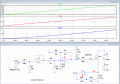
I am trying to make my own electronic load using ESP32, I am going to use either multiple IRFP260N or IXTK90N25L2 as the load mosfet. My question is

I am using a 50 amp 75 mv shunt and planning to use a 12bit DAC for the control signal and the attached schematic for the circuite.
As I am trying to enhance the control so I want to use an amplifier for the current measuring voltage signal (before the shunt).

Is this circuite correct or I have to add more elements.

Please note that my specialization is not electronicsSchematic_mosfet control_2021-03-30.png
 

ericgibbs

Joined Jan 29, 2010
18,766
hi Samy,
Welcome to AAC.
I guess you know that the U1:1 OPA will give you a Gain on 2 for the Rshunt voltage.?
E

BTW: What is U1 OPA type.?
 

Thread Starter

Samy.Amer

Joined Mar 30, 2021
20
Thank you, I was planning to change it to 39:1 to get 40x but forgot to update the image before attaching it.

I am planning to use either LM358 or LM324 if you have different recommendation please let me know
 

ericgibbs

Joined Jan 29, 2010
18,766
hi S,
This is a LTSpice sim of your circuit. LM324
E
Can you see the problem.?
We can refine the operation.

2nd Image has more detail.
 

Attachments

Last edited:

Thread Starter

Samy.Amer

Joined Mar 30, 2021
20
hi S,
This is a LTSpice sim of your circuit. LM324
E
Can you see the problem.?
We can refine the operation.

2nd Image has more detail.
In fact I was not sure if this circuite should work so difinatly we need to refine a lot of things in it.

And would you please explain the results of the simulator?
 

Thread Starter

Samy.Amer

Joined Mar 30, 2021
20
hi S,
This is a LTSpice sim of your circuit. LM324
E
Can you see the problem.?
We can refine the operation.

2nd Image has more detail.
Does this mean the current is fixed for all values of the control signal?

I was thinking of a problem as I taking the amplified voltage directly and comparing it with the control signal is this the issue?
 

ericgibbs

Joined Jan 29, 2010
18,766
hi Samy,
The circuit on the right hand side of this image shows the problem with your circuit.
To control that MOSFET from 0A to 50Amp Source current, requires a Vgate range of 4v thru 6V.

So with Vctrl =0 and Vshunt=0, a Vgate of ~4V is required.

E
I will relook at the circuit tomorrow.
 

Attachments

Thread Starter

Samy.Amer

Joined Mar 30, 2021
20
Thank you so much, Yes I am having a big CPU heatsink that will be temp controlled and the plan not to exceed 75c otherwise decrease the current or stop the test.

I have a question how to ensure that LTSpice is considering the linear mode of operation for the mosfet? as the whole operation lies in the linear region of the mosfet operation.
 

ericgibbs

Joined Jan 29, 2010
18,766
hi S,
As you may know the linear mode, does not mean that the Vg versus Id is linear over the full control range.
Look at these two images.
One shows the Vgate threshold voltage range [ The designer of the MOSFET LTS model chose 4V]
the other image shows the portion of the Vg curve which we are using in LTSpice.

As I noted you will have to use potentiometers in some fixed resistor locations in order to balance the circuit and get the performance you need.
MOSFET's of the same type could be vary over the ranges shown on the datasheet.

E
 

Attachments

Top