 Facebook
 Google
 GitHub
 Linkedin
Hi, I'm new here and i'm looking for peple that have some hnowledge into EMI.
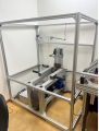
I am reaching out to you because I work in an small company specializing in machining, and we lack the in-house expertise to resolve this type of issue. Activating the frequency converter creates electromagnetic interference, which disrupts the electrical valve of the pneumatic cylinder and the Arduino.
The pneumatic part of the bench is controlled by an Arduino microcontroller. The Arduino program works correctly when the frequency converter (single-phase to three-phase) is connected but in the "off" position. However, as soon as the converter is turned "on," the Arduino and the valve become unstable, and the control section functions erratically.
We have tried several solutions to resolve this issue, and here are our findings:
The next steps I am considering to solve this are:
Thank you very much for your time.
I am reaching out to you because I work in an small company specializing in machining, and we lack the in-house expertise to resolve this type of issue. Activating the frequency converter creates electromagnetic interference, which disrupts the electrical valve of the pneumatic cylinder and the Arduino.
The pneumatic part of the bench is controlled by an Arduino microcontroller. The Arduino program works correctly when the frequency converter (single-phase to three-phase) is connected but in the "off" position. However, as soon as the converter is turned "on," the Arduino and the valve become unstable, and the control section functions erratically.
We have tried several solutions to resolve this issue, and here are our findings:
- Moving the Arduino outside of the metal cage improves its operation; however, the valve still switches randomly.
- If I am in contact with the metal cage and touch a component of the Arduino, it becomes unstable again.
- Connecting the converter to a different power outlet in the company makes no difference.
- If I connect the converter to a battery (see battery link), I no longer experience interference issues.
- Adding an EMI filter upstream of the converter produces no noticeable improvement (see EMI filter link).
- Moving the frequency converter out of the room does not change anything.
The next steps I am considering to solve this are:
- Installing an EMI filter on the output of the frequency converter.
- Using shielded cables for the connections entering and exiting the converter.
Thank you very much for your time.
Attachments
-
213.8 KB Views: 27
-
 495.8 KB Views: 31


