Electromagnet

Thread Starter

Annie Vaws

Joined May 1, 2026
32
What I think it seems like youbare doing is switching off the power supply, BUT NOT disconnecting the electromagnet. SO OF COURSEthe release will be slower!
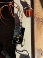
we have a little switch wired into the circuit - a push button switch. I press that quickly to simulate the lip movement. Even that gets hot!

a photo of the set up is attached. Excuse the messy wires for now this is a temporary set up.
 

Attachments

MisterBill2

Joined Jan 23, 2018
27,641
Really, you need to measure the RESISTANCE of the original coil and the new coil. Use an accurate meter with a scale that provides at least ten ohms resolution. Most heating is caused by power lost in the resistance, and so resistance is the independent variable that you can directly control. Most analog multimeters provide reasonable resolution only in the lower quarter of the ohms scale, at best.

And certainly the wire sizes look to be TOO SMALL!!
 
Last edited:

MrChips

Joined Oct 2, 2009
34,866
From what I can see, you have wired the switch incorrectly. If the switch is wired across the power supply then you are shorting the power supply and the switch will get hot.

You need to wire the switch in series with a high wattage resistor which will limit the current.
 

Thread Starter

Annie Vaws

Joined May 1, 2026
32
From what I can see, you have wired the switch incorrectly. If the switch is wired across the power supply then you are shorting the power supply and the switch will get hot.

You need to wire the switch in series with a high wattage resistor which will limit the current.
Thanks for the info.
Sorry to be a novice but please could you show me which wires need to connect to which to wire in series?

Also, which value resistor would you recommend please?

Thanks in advance
 

Thread Starter

Annie Vaws

Joined May 1, 2026
32
Really, you need to measure the RESISTANCE of the original coil and the new coil. Use an accurate meter with a scale that provides at least ten ohms resolution. Most heating is caused by power lost in the resistance, and so resistance is the independent variable that you can directly control. Most analog multimeters provide reasonable resolution only in the lower quarter of the ohms scale, at best.

And certainly the wire sizes look to be TOO SMALL!!
The wire size is identical to the original, 0.19mm.
 

B-JoJo-S

Joined Jan 3, 2026
342
It certainly looks as though the switch shorts the power supply when pressed.
I agree.
certainly the wire sizes look to be TOO SMALL!!
It has been said before that you should use a very small wire for the coil. @MisterBill2 makes a good point worth repeating: The wire size IS too small for the job. Not for the coil; but for the control of the electromagnet.
 

Thread Starter

Annie Vaws

Joined May 1, 2026
32
I agree.

It has been said before that you should use a very small wire for the coil. @MisterBill2 makes a good point worth repeating: The wire size IS too small for the job. Not for the coil; but for the control of the electromagnet.
Ok. So what size would everyone recommend please? We have tried
32 and 36 SWG with the same result.
 

B-JoJo-S

Joined Jan 3, 2026
342
Wire it this way: Forget the diode. You'll still have the slow release but I'm chasing after it.Screenshot 2026-05-25 at 8.38.28 AM.png
I DO have a different approach - space permitting. I'll post a picture in a few.

OK, EDIT: @Danko beat me to the punch.
 

MisterBill2

Joined Jan 23, 2018
27,641
The wire size is identical to the original, 0.19mm.
Not the coil wire sizes, but all of the interconnect wires that show in the photo. They appear to be very thin.
If the coil consumes the same current as the original coil but becomes much hotter in the same time as the original, and if the resistance is actually the same, then there is some hidden difference that we are not aware of. Have you actually measured the current flowing in the coil that becomes so hot?? Have you actually measeured the current in the other coil, the one that does not overheat so rapidly??
Possibly better thermal conductivity, or maybe just greater heat absorbing mass is the difference.
 

B-JoJo-S

Joined Jan 3, 2026
342
I was thinking of a purchased product such as Danko linked to. But I also had a different idea. Using a DC motor with an armature attached to the linkage and a return spring such as is pictured below (worked up from the previous drawing):
Screenshot 2026-05-25 at 9.05.53 AM.png
A DC motor will have some torque. Hopefully enough to actuate the lip. When you push the button it will pull the lip down. When released the spring will return the lip to the closed position. You shouldn't have any delay in the return as long as the spring is strong enough to close the lip but not so strong as to prevent the motor from trying to rotate some (maybe) 25 to 30 degrees clockwise.
 

B-JoJo-S

Joined Jan 3, 2026
342
I would recommend switching from 48VDC to 12VDC and use a 12VDC motor. Two things a lower voltage will do for you - it will lower the wattage, preventing some of the heating; and it will be easier to control. You could even go as low as 6VDC.

Properly wiring the switch (not shorted as in your picture) should be your first step. If everything works satisfactorily then there's no need for further change. The reason why your switch is getting hot is because you are dead-shorting it. THAT's the first thing that needs to be remedied.
 

B-JoJo-S

Joined Jan 3, 2026
342
Many years ago I read in one of those electronics magazines (Popular Electronics, Radio Electronics etc.) where someone made a wooden head (profile using 1/2" thick wood with lips that moved. The author used a DC motor to actuate the lower lip giving it the allusion of speaking. In his project I think he used an Op-Amp and some power transistors to move the lips. A low signal would move the lips slightly and a louder (higher) signal would open the mouth significantly more.
 

ThePanMan

Joined Mar 13, 2020
925
Thank you for the advice. I guess I’ll need to get a multimeter?
You're welcome. Just for clarity I'm talking only about the electromagnet being of smaller gauge wiring. Smaller and greater number of turns.

I'm liking what Jojo has to say using a motor instead of a magnet. AND lowering the voltage. Certainly a lower voltage would reduce the heat. Remember, you're re-engineering this project. You may be limited to space but you are not required to use the same approach, same voltage.
 

ThePanMan

Joined Mar 13, 2020
925
Many years ago I read in one of those electronics magazines (Popular Electronics, Radio Electronics etc.) where someone made a wooden head (profile using 1/2" thick wood with lips that moved. The author used a DC motor to actuate the lower lip giving it the allusion of speaking. In his project I think he used an Op-Amp and some power transistors to move the lips. A low signal would move the lips slightly and a louder (higher) signal would open the mouth significantly more.
I think I remember that article.
 

MisterBill2

Joined Jan 23, 2018
27,641
I think that the torque ofthe typical hobby classsmall DC motor is being OVER-ESTIMATED by a bit. Maybe even quite a bit. So I suggest investigating how much effort will actually be required. An arrangement that provides a mechanical advantage could make it work, but what I see in that sketch provides no mechanical advantage at all.
In addition, the stall current of a small motor is a lot more than the running current, and the scheme shown will not even allow a single revolution of the motor.
AND, since this is intended to move the lip of some puppet, there will be instances where it is active for at least a few seconds. So overheating would be a problem.
 

ThePanMan

Joined Mar 13, 2020
925
ChatGPT says: "Hands-On Electronics featured projects like Fred the Head, a talking head model.
Fred the Head is a unique project that combines electronics and creativity, allowing users to create a wooden head that mimics speech through synchronized jaw movement. This project utilizes a circuit board that incorporates an operational amplifier (op-amp) and a motor to achieve the jaw's movement in time with audio input, making it appear as if the head is talking."
The article can be found below.
https://www.scribd.com/document/520295472/fred-the-head-1989-wooden-talking-and-head-project
Notice @MisterBill2 the jaw is counterbalanced. An opposing force such as the spring can hold the mouth closed until the motor is activated. The weight of the spring would become critical so as to not overpower the motor. I'm liking the idea. Perhaps this is a good project for my nephews and nieces. "Uncle Pete made a robot that speaks". I can hear that now.

AHHHhhhhh. That was a good read. Takes me back. Way back. Though I would have thought it was well before 1989. If I were to guess I would have said 1982, 83 or 84.
 
Last edited:
Top