Electromagnet waveform

Thread Starter

cmartinez

Joined Jan 17, 2007
8,762
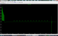
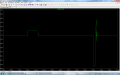
Ok... I decided to go empirical here, and what I did is I changed the value of C1 to 0.22 µF, and what happened is that R7 dissipated more power than previously estimated (1/3 W vs around 1/4 W)
So I changed R7 to 470 Ω , and it's now only dissipating about 1/5 W
So what I'm going to do now is make C1 = 0.22 µF and R7 = 470 Ω @ 1/2 W and see how things work out...
 

ronv

Joined Nov 12, 2008
3,770
Actually, I'm not sure we even need it now that I look a little closer. :oops:
I think it was a leftover from one of the earlier try's.
I think I was trying to hold the voltage down before adding the diode and TVS.
 

Thread Starter

cmartinez

Joined Jan 17, 2007
8,762
Actually, I'm not sure we even need it now that I look a little closer. :oops:
I think it was a leftover from one of the earlier try's.
I think I was trying to hold the voltage down before adding the diode and TVS.
Mmmhhhh... thanks for sharing...
So, if I were to remove that RC snubber from the circuit, do you think the effects will show in the simulation?
 

Thread Starter

cmartinez

Joined Jan 17, 2007
8,762
So I removed the RC snubber at the coil, and the voltage stayed exactly the same throughout the simulation... except at the very end, when an ugly 40V spike (and some ringing) appeared, right after the final -75V pulse.... I think I'm gonna keep that snubber in there... unless you have a better idea, of course.
 

Attachments

Thread Starter

cmartinez

Joined Jan 17, 2007
8,762
Well, I've already ordered all the parts, and finished the power supply's PCB. Right now I'm working on the valve driver's PCB.
Anyway, I just wanted to ask, how hard would it be to add current limiting, and/or protect the device from short circuits? I'm not talking about the power supply but about the driver.
 

ronv

Joined Nov 12, 2008
3,770
I think you can do it in code since we have the current coming out you could probably do a check at the beginning of the turn on and see that you have some current, if not, shut down as a safety feature for having it unplugged and then check that it didn't go over say 9 amps for the over current. Maybe do that twice, once at the start and once after high power is off.
Whatca think?
 

Thread Starter

cmartinez

Joined Jan 17, 2007
8,762
I think you can do it in code since we have the current coming out you could probably do a check at the beginning of the turn on and see that you have some current, if not, shut down as a safety feature for having it unplugged and then check that it didn't go over say 9 amps for the over current. Maybe do that twice, once at the start and once after high power is off.
Whatca think?
Yeah... already thought of that, but wanted your opinion anyway... and yes, that's probably the simplest way. Gonna probably need two comparators though, one for monitoring the 120V pulses and another one for the plateau... either that or use an ADC... but I'm trying to avoid that. Thanks!
 

ronv

Joined Nov 12, 2008
3,770
Hmm, let me think about that. I'm still having some trouble figuring out how you are going to do the pwm on the 120 volt supply without an A to D. Will you build an external triangle or sawtooth circuit?
The 12 volts is easy, but the 120 I think is more complex.
 

Thread Starter

cmartinez

Joined Jan 17, 2007
8,762
Hmm, let me think about that. I'm still having some trouble figuring out how you are going to do the pwm on the 120 volt supply without an A to D. Will you build an external triangle or sawtooth circuit?
The 12 volts is easy, but the 120 I think is more complex.
Don't worry about that... the PWM will be generated directly from the MCU, at any frequency and any duty cycle that I choose... I'd just like to make sure that we're not working things in short circuit, just for safety, if possible. But then again the use of a comparator might be the simplest solution to that.
 

ronv

Joined Nov 12, 2008
3,770
Don't worry about that... the PWM will be generated directly from the MCU, at any frequency and any duty cycle that I choose... I'd just like to make sure that we're not working things in short circuit, just for safety, if possible. But then again the use of a comparator might be the simplest solution to that.
But don't you need to know the current to know how long to leave it on?
 

Thread Starter

cmartinez

Joined Jan 17, 2007
8,762
But don't you need to know the current to know how long to leave it on?
Ahhh.... I see what you mean... I could use the comparator for the plateau, since it will be at constant current. But at the initial 120VDC PWM I won't know what's going on... but that's only for 1/2 ms... I'll have to think about that too... thanks
 

ronv

Joined Nov 12, 2008
3,770
Here is a thought. It uses a simple rc to generate a curve, then pwms around it. You can change coil resistance and it still gets there in about the same time. I didn't try changing voltage on the 120 and 12, but I suspect it will work for that. You could probably control it with a port pin.
PS. If you don't have a 339 model you can use a comparator from the regular spice files.
 

Attachments

Thread Starter

cmartinez

Joined Jan 17, 2007
8,762
Here is a thought. It uses a simple rc to generate a curve, then pwms around it. You can change coil resistance and it still gets there in about the same time. I didn't try changing voltage on the 120 and 12, but I suspect it will work for that. You could probably control it with a port pin.
PS. If you don't have a 339 model you can use a comparator from the regular spice files.
Thanks! it looks very interesting... I'm going to play a bit with it and then get back to you.
 

Thread Starter

cmartinez

Joined Jan 17, 2007
8,762
Just thought I'd let you know that I finally got the pieces. I've already designed the 120VDC power supply PCB, and I'm about to get started with the driver's PCB. It's assembly and testing after that.


AnW4qxWn2gM7kJfLbGxbwM_Rr0pst2L5NSFGQD-218TZ.jpg
 
Top