Facebook
 Google
 GitHub
 Linkedin
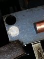
Can't recall ever seeing that, but the graphite we used was very hard, dense and abrasive. It was made from residue from oil refining. They also had some with copper powder incorporated in it.I am not into EDM, but have you used "glassy" carbon as the electrode. It is quite hard and "like glass." That is, it can be polished to a very smooth and non-absorptive surface. I used it as an electrode in an electrochemical cell for an HPLC detector many years ago. My company wouldn't patent it, and Beckman stole it. Fortunately, we were still able to use it without paying royalties.
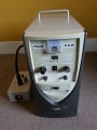
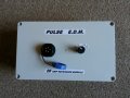
EDM - Electrical discharge machine
- Thread starter shortbus
- Start date