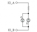
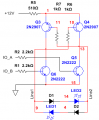
Good questions. It vas idea only. Now I finished simulation. Seems R5 = 1.2 k as current limiter is too big - current is 0.7 mA only.
When resistor R5 = 100 Ohm, LED's current is 20 mA. View attachment 141136
According to the theory that the Vf of LED will be less than Vbr(breakdown), so when they connected with pin to pin and one of the LED is reverse the polarity, so no need two diodes, only need the diodes when the LEDs in series with a current limiting resistor and then in parallel together.
OK. You can see how small LEDs current. And I used in simulation red LEDs. They have forward voltage 2V. How about 3...3.5 V for white LEDs ? I think you need increase voltage for LEDs feeding. Maybe up to 9...12 V.
There was a message replied to -- ElectricSpidey said: ↑
So that wasn't replied to you.
And I mentioned that because the circuit was too simple and could be damage the LEDs, specially when he didn't considering the voltage came from the inputs side.
OK. You can see how small LEDs current. And I used in simulation red LEDs. They have forward voltage 2V. How about 3...3.5 V for white LEDs ? I think you need increase voltage for LEDs feeding. Maybe up to 9...12 V.
I just thought about a simple issue, if the inputs current is enough to providing what the LEDs need then probably only need one resistor and two LEDS and it's done, what do you think about this point?
According to the theory that the Vf of LED will be less than Vbr(breakdown), so when they connected with pin to pin and one of the LED is reverse the polarity, so no need two diodes, only need the diodes when the LEDs in series with a current limiting resistor and then in parallel together.
I just thought about a simple issue, if the inputs current is enough to providing what the LEDs need then probably only need one resistor and two LEDS and it's done, what do you think about this point?
I do not like it. Because for V forward=3V for white LEDs and V inputs = 3.3 V we need to put resistor R = (Vinp - Vled) / Iled then
R = (3.3 - 3) / 0.02 = 15 Ohm. In this case, if line will suddenly shorted we can have fried logic gates.
And more: I am trying to solve problem in general case. Tomorrow they will need to light 300 mA LEDs and my solution will help them.
I do not like it. Because for V forward=3V for white LEDs and V inputs = 3.3 V we need to put resistor R = (Vinp - Vled) / Iled then
R = (3.3 - 3) / 0.02 = 15 Ohm. In this case, if line will suddenly shorted we can have fried logic gates.
And more: I am trying to solve problem in general case. Tomorrow they will need to light 300 mA LEDs and my solution will help them.
OK. You can see how small LEDs current. And I used in simulation red LEDs. They have forward voltage 2V. How about 3...3.5 V for white LEDs ? I think you need increase voltage for LEDs feeding. Maybe up to 9...12 V.
The 1k resistor allows a microcontroller signal voltage to manage the PNP just fine.
The design above with a resistor below the bridge screws up signal control of the PNP
The cost of a single relay is dirt cheap.. usually less than $2 and done..
They have spent more time (= money) trying to figure out a way to not just spend the $2..
Makes no sense to me to not do it and be done..
The cost of a single relay is dirt cheap.. usually less than $2 and done..
They have spent more time (= money) trying to figure out a way to not just spend the $2..
Makes no sense to me to not do it and be done..
Is this some kinds of commercial product?
If it is not, why you care so much about the cost since many circuits won't cost much?
How many mA that the uC could provides?
Did you see the posted #52, is it doesn't match your application, why?
Is this some kinds of commercial product?
If it is not, why you care so much about the cost since many circuits won't cost much?
How many mA that the uC could provides?
Did you see the posted #52, is it doesn't match your application, why?
It’s a prototype at this stage. We are just testing out different part of a design. Could lead to a commercial, I hope.
So the lower the cost, the better.
I totally understand why you suggest the circuit on post #52. In our application, we may need to drive 4 leds instead of 2. (Still two color, but 2 will be in serial). So I may prefer the h-bridge solution.
I can see what your suggested on post #52 is perfect for some other application.
Or maybe it’s the Chinese in me, I always want to do thing cheaper if possible

 Facebook
 Google
 GitHub
 Linkedin