Facebook
 Google
 GitHub
 Linkedin
Hello everybody, I could use some help with a project I 'm working on.
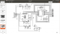
I have a up/down counter, to be specific its the Velleman kit K8035.
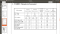
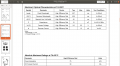
It 's working fine, but now I have to make it work with Large 7 segment display, KYX-40101AS.
Can anybody help with the circuit I need to drive those Big Display and make them work with the K8035 kit?
Thank You!
I have a up/down counter, to be specific its the Velleman kit K8035.
It 's working fine, but now I have to make it work with Large 7 segment display, KYX-40101AS.
Can anybody help with the circuit I need to drive those Big Display and make them work with the K8035 kit?
Thank You!
Attachments
-
373.6 KB Views: 49
-
138.5 KB Views: 50