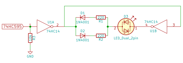
Driving a bi-color LED from one MCU pin

Thread Starter

ilium007

Joined Aug 24, 2013
139
Working (don't mind my lack of protoboard skills - it's midnight)


But.... I just read this on another forum:

"You should never put LEDs directly on logic signals. They have a lot of capacitance and will make your logic signals very ugly. If you ever get a chance to look at it on a scope you will see what I mean."
 

GopherT

Joined Nov 23, 2012
8,009
But.... I just read this on another forum:

"You should never put LEDs directly on logic signals. They have a lot of capacitance and will make your logic signals very ugly. If you ever get a chance to look at it on a scope you will see what I mean."
Are you driving them at MHz or just low frequency switching (few few khz or less).
 

dendad

Joined Feb 20, 2016
4,641
You will only need D1 and D2 so you can have R1 and R2 different values. Otherwise only one resistor is needed and the diodes can be removed.
And I think a pullup may be better than a pull down. Some bus expanders have pullups included so if you have a pullup and pull down the result may be more undefined. Still, whatever works :)
 

Thread Starter

ilium007

Joined Aug 24, 2013
139
You will only need D1 and D2 so you can have R1 and R2 different values. Otherwise only one resistor is needed and the diodes can be removed.
And I think a pullup may be better than a pull down. Some bus expanders have pullups included so if you have a pullup and pull down the result may be more undefined. Still, whatever works :)
In the schematic I made both resistors the same value but until I have the actual LED I am going to use I can't decide on the values.

I have to find light pipes first then I can choose an LED.
 

Thread Starter

ilium007

Joined Aug 24, 2013
139
Some bus expanders have pullups included so if you have a pullup and pull down the result may be more undefined. Still, whatever works :)
I am thinking about just using the 74HC595 shift registers instead of bus expanders for ease of use. Haven't decided yet.
 
For original poster an for future reference, here is a solution that I had made after searching the interenet for a similar issue.
I have attached the PDF of a charging circuit, and here is a short video I made about it:
So in short, you can drive two leds with one pin.
In my case, I used a single inverter, in your case, you can use a 74ls04 hex inverter. You may need a few of them though ;)

I know it is a very late reply, but might as well be added for prosperity.
 

Attachments

Top