Driving a bi-color LED from one MCU pin

dendad

Joined Feb 20, 2016
4,641
I could just build enough boards to get double the outputs and then find three lead red/green LED's and use two pins per LED. Would be easier than trying to get the 2 lead ones working but wastes a lot of I/O.
If you are going to use 2 port pins, use the 2 pin bicolour LEDs and hook them in series with a resistor between the pins. On hi, one low = Red, swap = Green, both the same off.
Although if you use 3 pin ones, both on = yellow.
 

Thread Starter

ilium007

Joined Aug 24, 2013
139
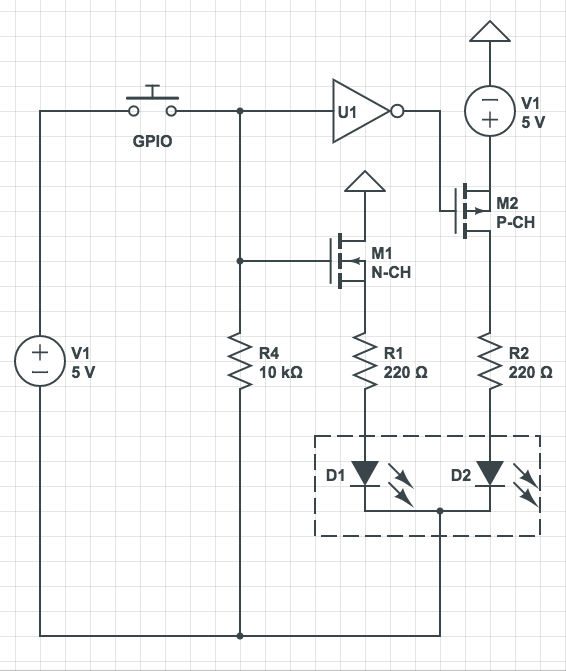
What about this. I used Circuit Lab because it was quick and easy (I know it is not 100% correct).

I have found 3mm common cathode red/green LED's - 3 leads. If I use a simple logic inverter driving N channel and P channel MOSFETs.

If the GPIO pin is low then the inverter output is high and M2 (P channel MOSFET) is driven and current flows to one LED via a current limiting resistor, R2.

If the GPIO pin is high then the inverter stops the gate drive on M2 and drives the gate on M1 which sinks current via R1 to the other LED.

Each resistor could be different to ensure equal brightness of the LED's.

The MOSFET gates may need a 1k series resistor as well, not sure. I know its more complex but would this work ?

**removed schematic because it was wrong**
 
Last edited:

Alec_t

Joined Sep 17, 2013
15,149
Here's an option if you need only a modest LED current:
Bi-colorLEDs.PNG
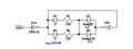
1 port pin per dual-LED. D1 and D2 enable the use of different series resistors for the red and green LEDs, if you find that's necessary to balance the brightness.
One IC contains 6 gates so can drive 3 dual-LEDs.
 

Thread Starter

ilium007

Joined Aug 24, 2013
139
Here's an option if you need only a modest LED current:
View attachment 138283
1 port pin per dual-LED. D1 and D2 enable the use of different series resistors for the red and green LEDs, if you find that's necessary to balance the brightness.
One IC contains 6 gates so can drive 3 dual-LEDs.
I'll have a look at the current sink capability of that IC (I have one here as well to test !) but I think the total package current sink is small.
 

Thread Starter

ilium007

Joined Aug 24, 2013
139
It looks like sink/source current on the 74HC14 is limited to 25mA so I would be back to the small MOSFETs to drive all LED's off the one inverter.
 

Thread Starter

ilium007

Joined Aug 24, 2013
139
Thats essentially the same circuit as I had but I need to be careful of the GPIO current sink ability. I am going to be building the final project on a Teensy 3.6 with and I don't want to go over 10mA current sink on the GPIO pins, if I use a MCP23S17 to expand ports I am limited again to the total current sink ability of that IC which wont support all channels running at 20mA at once.

Thats what I looked at using the small MOSFETs or even transistors. I don't know how to calculate base resistor values for the transistors so I went with the MOSFET's (I'm a pilot, not an electrical engineer !)

I love the simplicity of the inverter circuit !
 

dendad

Joined Feb 20, 2016
4,641
What about this. I used Circuit Lab because it was quick and easy (I know it is not 100% correct).

I have found 3mm common cathode red/green LED's - 3 leads. If I use a simple logic inverter driving N channel and P channel MOSFETs.

If the GPIO pin is low then the inverter output is high and M2 (P channel MOSFET) is driven and current flows to one LED via a current limiting resistor, R2.

If the GPIO pin is high then the inverter stops the gate drive on M2 and drives the gate on M1 which sinks current via R1 to the other LED.

Each resistor could be different to ensure equal brightness of the LED's.

The MOSFET gates may need a 1k series resistor as well, not sure. I know its more complex but would this work ?

The short answer is , No!

M1 and M2 should both be the same N chan FETs running of the single +5V supply.
 

dendad

Joined Feb 20, 2016
4,641
Thats essentially the same circuit as I had but I need to be careful of the GPIO current sink ability. I am going to be building the final project on a Teensy 3.6 with and I don't want to go over 10mA current sink on the GPIO pins, if I use a MCP23S17 to expand ports I am limited again to the total current sink ability of that IC which wont support all channels running at 20mA at once.

Thats what I looked at using the small MOSFETs or even transistors. I don't know how to calculate base resistor values for the transistors so I went with the MOSFET's (I'm a pilot, not an electrical engineer !)

I love the simplicity of the inverter circuit !
Put an extra inverter between the Teensy and the first LED as a buffer.
One 74HC04 package will than be running 3 LEDs at a time.
If you are worried about the total package current, make the resistors 270R, 330R or 390R. See how bright the LEDs are.
Try it and see.

I must go to bed ;)
Please post your final design and how it all works.
 

dendad

Joined Feb 20, 2016
4,641
I could not just get to sleep. A cuppa sounds good first.
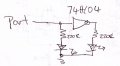
If you go with the 2 pin LEDs it will save wire and so run 2 of the inverters in series with the LED and its resister across the second one.
The first inverter is to protect the processor pin. Add a pullup resistor to the processor supply on the first inverter input. I'm fairly sure you can run the input on 3.3V from the Teensy and still have the 74HC04 running off 5V ok.
 

Thread Starter

ilium007

Joined Aug 24, 2013
139
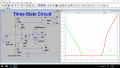
Is this the circuit from above you are referring to ?


I can see U1a is protecting the MCU but where is the circuit sinking its current to ? It looks like the inverter is doing the sourcing / sinking of current.

A hex inverter would mean 3 LED's each at 20mA - I need to look at the spec sheets and see if the package will support the current and thermal requirements but this might be the go !
 
Last edited:

MrChips

Joined Oct 2, 2009
35,031
Another solution uses an H-bridge implemented with a pair of inverters (NOT gates) such as 74LS04 or any 74xx04. However, this will require two control signals per LED pair.
 

Thread Starter

ilium007

Joined Aug 24, 2013
139
The 74HC14 is limited to 50mA but I don't have to run these LED's at 20mA, I'm sure 10mA - 15mA would be fine.

I'll build a circuit at give it a go !
 

Thread Starter

ilium007

Joined Aug 24, 2013
139
Another solution uses an H-bridge implemented with a pair of inverters (NOT gates) such as 74LS04 or any 74xx04. However, this will require two control signals per LED pair.
Yeah, if I go to 2 GPIO pins I may as well just use a small MOSFET on the output and control the switching in code. I was just trying to save 60 I/O channels.
 

Thread Starter

ilium007

Joined Aug 24, 2013
139
The 74HC14 is limited to 50mA but I don't have to run these LED's at 20mA, I'm sure 10mA - 15mA would be fine.

I'll build a circuit at give it a go !
It works fine and LED lit bright enough at 6mA (I only had 470 Ohm resistors on hand).

I had to put a 10k resistor on the inverter input 1 to tie it to GND to prevent it floating but other than that it works !
 
Top