Facebook
 Google
 GitHub
 Linkedin
MaxHeadRoom
- Joined Jul 18, 2013
- 30,699
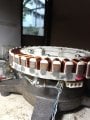
I don't have any info on a drive, at least for the Fisher-Paykel version, they do posses the 3 commutation feedback devices,Do either of you have the info on this driver. I know this post is >365 days and the odds are against me")