Facebook
 Google
 GitHub
 Linkedin
Hello everyone,
I'm just looking for a sanity check. I want to drive a 5V LED strip using one of the RGB outputs of a 5V WS2811 module.
I found this discussion, which is for a 24V supply using a PNP transistor:
https://forum.allaboutcircuits.com/...using-ws2811-to-switch-pnp-transistor.203523/
The WS2811 has three output pins. Each output is a PWM controlled constant-current sink (about 18mA). An LED is connected to 5V and the WS2811 output. When the PWM is "on" it allows 18mA to flow through the LED. When "off" it does not allow current to flow. The LED is usually one third of a single RGB LED package, but it's easy enough to use the three outputs to drive three discrete LEDs. I want to use a daisy-chain of WS2811 chips to drive some individual LEDs, and some 5V LED strips of maybe 20 LEDs. It is convenient to use 5V everywhere, but a WS2811 can not drive an LED strip without some sort of buffer.
There are several examples online using MOSFETs to drive long strings of LEDs, with an inverting stage (because of the inverse sense of PWM switching versus LED "on" state). If everything is 5V, and current requirements are limited then a single PNP transistor ought to work.
So here's my design.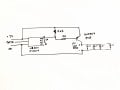
The 4k7 resistor pulls the transistor base high when PWM is not driving. The 180R resistor allows the full 18mA of current to flow through the WS2811, and fully saturate the transistor. The transistor is rated at about 600mA, which is sufficient to drive about 30 LEDs in a strip at about 20mA each, although I intend to limit my use to about 20 LEDs.
I have built this, and it works, but I have not measured any voltages or currents in the assembled circuit. I'd like to hear opinions on the design, especially if there are any ideas to improve it. The end goal is to control several individual LEDs and several "illuminated areas" across a panel about A4 size with a single 5V supply and a single control interface.
Thank you.
I'm just looking for a sanity check. I want to drive a 5V LED strip using one of the RGB outputs of a 5V WS2811 module.
I found this discussion, which is for a 24V supply using a PNP transistor:
https://forum.allaboutcircuits.com/...using-ws2811-to-switch-pnp-transistor.203523/
The WS2811 has three output pins. Each output is a PWM controlled constant-current sink (about 18mA). An LED is connected to 5V and the WS2811 output. When the PWM is "on" it allows 18mA to flow through the LED. When "off" it does not allow current to flow. The LED is usually one third of a single RGB LED package, but it's easy enough to use the three outputs to drive three discrete LEDs. I want to use a daisy-chain of WS2811 chips to drive some individual LEDs, and some 5V LED strips of maybe 20 LEDs. It is convenient to use 5V everywhere, but a WS2811 can not drive an LED strip without some sort of buffer.
There are several examples online using MOSFETs to drive long strings of LEDs, with an inverting stage (because of the inverse sense of PWM switching versus LED "on" state). If everything is 5V, and current requirements are limited then a single PNP transistor ought to work.
So here's my design.
The 4k7 resistor pulls the transistor base high when PWM is not driving. The 180R resistor allows the full 18mA of current to flow through the WS2811, and fully saturate the transistor. The transistor is rated at about 600mA, which is sufficient to drive about 30 LEDs in a strip at about 20mA each, although I intend to limit my use to about 20 LEDs.
I have built this, and it works, but I have not measured any voltages or currents in the assembled circuit. I'd like to hear opinions on the design, especially if there are any ideas to improve it. The end goal is to control several individual LEDs and several "illuminated areas" across a panel about A4 size with a single 5V supply and a single control interface.
Thank you.