 Facebook
 Google
 GitHub
 Linkedin
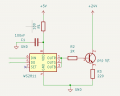
I am designing a device for some laboratory work where I need to apply different temperatures to dozens of different samples. I am planning to use WS2811s (1 wire LED drivers) to simplify the wiring. The idea is to use one WS2811 (which sinks up to 18mA of current per channel) per heater, to switch on a PNP and run approximately 100mA of current through R3 (220 Ohms). This resistor is used as a heating element. (See Diagram). (R1 and C1 are just recommended by the WS2811 data sheet).
The WS2811 is designed to be used at maximum of 12V - but I’m assuming that this is for direct connection to LEDs which are only dropping 3V. I would like to use a 24V supply for the heating - as I can more easily find a cheap switching power supply that can handle the 3 or 4 Amps I will need for all the heaters. If I put a current limiting resistor at the base of the PNP, so that there can never be more than 10mA sinking into the WS2811 - I think I should be able to still switch on the PNP and drive approximately 100mA through R2.
Does this seem OK? I only have a few through hole WS2811s to breadboard so wanted to check before prototyping it !
Attachments
-
 81.2 KB Views: 15


