extremely strange circuit behavior - looking for an advice

Thread Starter

thor21

Joined Sep 29, 2024
421
hello,
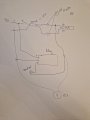
I am measuring Volts on "relatively" simple circuit as follow
power supply (12) -> switch (see pdf) -> led stripe.

When the switch is off ie led strip is not producing any light and i measure Voltage
1)
+ and i pole : directly on Led stripe or on the part of the switch which is connected to stripe i have 0V

2)
+ pole on the led stripe
- directly on power supply ie input part of the switch
i measure 12V
even the stripe is off

Any idea why i am getting 12V in case i directly use ground from the psu?

Thank you so much!


switch
https://www.t-led.cz/media/doc/prod/Instructions/Uživatelský návod stmívač 8AS 2023.pdf
 

BobTPH

Joined Jun 5, 2013
11,463
You are measuring across the switch which is in series with the battery and the strip. 12V is exactly as expected. You are basically measuring the battery voltage through the resistance of the strip. Since the meter has a very high resistance, the strip resistance has no effect.

If you want to measure the voltage seen by the strip, place the two probes on the two terminals of the strip.
 
Last edited:

Thread Starter

thor21

Joined Sep 29, 2024
421
@BobTPH
which battery do you mean? Dont get it ... ;/ why across the switch? I am measuring + pole on led strip (which is 0V in case switch is off)

Okay, maybe need to add more context...
I have another device ie relay which is powered by 12V and has Signal input socket; once signal input is on ie 12V for example,
there relay is on...


So my initial thought was:
1) power relay from the same psu as a strip 12V
2) take plus ( + ) pole from the led strip - as a Signal to control relay
- so in case the strip is powered off relay is off
- in case strip is on - Signal to switch relay on

Currently i am getting constantly relay on - even the strip is off bc i am measuring there constant 12V

the relay module is here>
https://dratek.cz/docs/produkty/1/1927/1700475986s_1700646270s_1476828250s.pdf


thanks!
 

BobTPH

Joined Jun 5, 2013
11,463
which battery do you mean? Dont get it ... ;/ why across the switch? I am measuring + pole on led strip (which is 0V in case switch is off)
I mean power supply.

You need to post a schematic showing your whole circuit and exactly where you placed the probes.

I may be misinterpreting your verbal description wrong, (that is why we use schematics) but from what I understand, 12V is the correct measurement. You are NOT measuring the voltage across the strip if thatp is what you think.
 

Alec_t

Joined Sep 17, 2013
15,101
Welcome to AAC!
As Bob says.
In case (2) the Voltmeter's very high input impedance is in series with the comparatively low impedance of the LED strip. The two impedances form a voltage divider, with most of the voltage appearing across the meter terminals.
 

Thread Starter

thor21

Joined Sep 29, 2024
421
Well,
So how can I control the relay ie turn it off /on based on the state of the led strip ie strip is on or off.

Is such a thing possible? Or do I have to use another psu to power relay circuit and take a plus pole as a control signal from the strip? Thanks!
 

Ya’akov

Joined Jan 27, 2019
10,226
Welcome to AAC.

Your relay module has a high impedance input—that is, it requires a voltage but very little current. Even though the 12V you are measuring could power almost nothing, your module only cares that there is at least 5V on it’s input.

The answer to the problem is to use a resistor to prevent the spurious voltage from turn on the relay. Since it only needs 5V, you just have to drop the voltage to something below that (approximately).

Alternatively, you can replace your SPST (Single Pole Single Throw) switch with a DPST (Double Pole Single Throw) version. This will let you switch both the 0V (-) and 12V (+) removing any phantom circuits.
 

Thread Starter

thor21

Joined Sep 29, 2024
421
Don't get it.

I the stripe is 12v and was told that module can be controlled even with 12v.

But how it's possible there is constantly 12v once I take a plus pole from the stripe to the relay control port.. Even the stripe is off?

How does resistor help? Still confused....
You control relay if there is 0v or 5/12v

Thx
 

BobTPH

Joined Jun 5, 2013
11,463
Here is the circuit you describe.

1727621030034.jpeg

A voltmeter behaves in a circuit like a large resistor. Typically 1M or 10M Ohms for modern digital meters.

It registers a voltage when a current flows through it. The LED strip is basically powered by the small current going through the meter. But the current is very small (microamps). So the LEDs do not light and all nearly all the voltage is across the much larger resistance of the meter. Hence the reading of 12V.

This is a classic voltage divider circuit. It is one of the first circuits analyzed in a basic electronics course.
 

BobTPH

Joined Jun 5, 2013
11,463
regarding your diagram - i dont think thats the way how to measure Volts. Volt meter should be placed in parallel to + and - poles...
Of course it is not! It is what you described and why you got a puzzling result. This is why we use schematics, apparently you can see that it is wrong in the diagram.

I asked you to draw what you actually did. I ask again. And make sure you measure again according to the diagram you draw.
 

Thread Starter

thor21

Joined Sep 29, 2024
421
@BobTPH
the diagram i wrote - ie how the things are connected and what i measured - all is written in that diagram.

I am confused... whats not clear? why to measure again? The measurements are according to my schema/diagram.

thanks
 

BobTPH

Joined Jun 5, 2013
11,463
Okay, I looked at the link for the “switch”. That is not a switch. A switch is an electromechanical device that makes or breaks a connection. Sorry for the confusion.

The so called “switch” is probably switching the - line, with the + line fed directly through. That would explain your reading.
 
Last edited:

Thread Starter

thor21

Joined Sep 29, 2024
421
@BobTPH
to fix that behavior, means that there suppose to be 0V on both meter readings.

Once the PWM (Switch) is on i want to send signal to relay ... but currently even the PWM (switch) is off there is constantly 12V as per the diagram.

thanks
 
Top