extremely noisy signal

Thread Starter

Slania87

Joined Jul 9, 2025
9
Hi!

I have to measure an electrical interference signal and it is very noisy. It derives from a DC stimulator, a 653 and 643 Hz signal.
The oscilloscope used: Digital Storage Oscilloscope 100MHz MP720665

The measurement setup:
Note: at the end of the probes and the stimulator outputs are silver electrodes.
Group 1, Grouped object


I tested it as follows:
1. Executed self calibration
2. Probes compensation: (3.3V/1kHz)
1754383783286.png

It looks fine for me.

3. For testing, I used two signals: 600 Hz and 610 Hz: (I can only upload one picture. It is the 600 Hz measurement. The 610 Hz and the interference of these two signals are fine.)


1754388577268.png


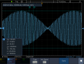
On the other hand, when I used the signals of 653 and 643 Hz, the signals are very noisy.

1754388059356.png

1754388107696.png

The interference:

1754388155759.png


These are very noisy.

Also, I measured the noise of the oscilloscope and the probes, they are very significant:

1754389033523.png
Also, when I took the probe between the two silver electrodes attached to the oscilloscope, there is also a significant noise, but it changed to measure the signal in ampere. The SECOND picture is the first 1000 elements of the signal.
1754389370306.png


Can You advise me anything in this matter?
 

Attachments

Last edited by a moderator:

MisterBill2

Joined Jan 23, 2018
27,164
ALL of the signals displayed are quite noisy! The very first signal appears to be less noisy, but it still contains a lot of noise..
So the reality is that we do not have nearly enough information to make useful suggestions. So now some questions: What is the reference that the waveforms are measured against?? are they all measured against the same point?? Are these signals from the same source?? What are the waves supposed to be? (Voltage, frequency, and current?)
 

Ian0

Joined Aug 7, 2020
13,097
What do you want to know about the signal? Amplitude? Frequency?
How long does it last for? The longer you measure it the more accurate you can get.
 

MisterBill2

Joined Jan 23, 2018
27,164
It would be handy to understand what the desired signal actually is, in addition to having answers to the questions about the measurements that I asked.
As an uninformed guess, the signals that we see may have been amplified in a circuit powered bt a very noisy zener shunt regulated power supply.
 

Thread Starter

Slania87

Joined Jul 9, 2025
9
Wh
ALL of the signals displayed are quite noisy! The very first signal appears to be less noisy, but it still contains a lot of noise..
So the reality is that we do not have nearly enough information to make useful suggestions. So now some questions: What is the reference that the waveforms are measured against?? are they all measured against the same point?? Are these signals from the same source?? What are the waves supposed to be? (Voltage, frequency, and current?)
The outcome should be regular sinusoidal waves at the given frequencies. My question is what can cause the distortion and noise at the frequency at 653 and 643 Hz?
Current is 450 µA.
 

Ian0

Joined Aug 7, 2020
13,097
Wh

The outcome should be regular sinusoidal waves at the given frequencies. My question is what can cause the distortion and noise at the frequency at 653 and 643 Hz?
Current is 450 µA.
It looks like white noise, it can be caused by noisy power supply, noisy amplifier. Turn up the timebase on the scope so that you can see the interference signal to see whether it has regular or random spikes. if they are regular and between 5us and 20us apart they are from a switched-mode power supply.
 

MisterBill2

Joined Jan 23, 2018
27,164
Next question: are all of those signals coming from the same source?? Is the source a single oscillator?? OR is it a synthesizer of some type??
Are you able to provide any information about the source of that signal???
One useful bit of information is that interference signals are often noisy.
AND another bit of information is that without additional explanation , you are not likely to receive other than random guesses!
 
Last edited:

Ian0

Joined Aug 7, 2020
13,097
Whilst it might be better if you can get rid of the noise, if the noise is part of the signal and all you want is the amplitude or frequency, then you can get that without removing the noise, given a bit of sampling and averaging.
 

MisterBill2

Joined Jan 23, 2018
27,164
A lot of noise looks like "white noise" initially. BUT that does not make it white noise. It can be from different non-correlated sources, centered around a number of different frequencies. Like the older PC computer noise was.
What it looks like to me is radio noise of a receiver not tuned correctly to the carrier frequency. It actually looks a lot like that.
 

Ian0

Joined Aug 7, 2020
13,097
On a digital scope it looks whiter than it is, because at a slow timebase whether a spike registers or not is random. Random spikes = white noise.
 

MisterBill2

Joined Jan 23, 2018
27,164
In addition, unless the sweep is made fast enough to display a waveform, there is no way to know what is actually present, other than the average peak value, which is seldom that useful.
 

MrAl

Joined Jun 17, 2014
13,667
Wh

The outcome should be regular sinusoidal waves at the given frequencies. My question is what can cause the distortion and noise at the frequency at 653 and 643 Hz?
Current is 450 µA.
Hi,

Can you repeat the test? This time, vary the frequency gradually and see where it kicks in first, then see where it stops as you go up in frequency. That would possibly isolate a band where the interference is present. We'd want to know where it starts and stops just in case it has two or more strong regions.

It can be from something nearby or even the power supply in something. Switchers can be very noisy. So are computers, laptops, tablet computers, etc. The noise might be always there but you might only see it with the scope set at certain settings.
 

MisterBill2

Joined Jan 23, 2018
27,164
OK, one more thing is that if there is not adequate shielding from all the external sources you will certainly pick up a great amount of noise. ALL of the enclosure MUST be tied to the signal sources common connection, and all of the signal wiring must also be screened (shielded). This has been verified in over 60 years of experience.
 

Ian0

Joined Aug 7, 2020
13,097
I have to measure an electrical interference signal and it is very noisy. It derives from a DC stimulator, a 653 and 643 Hz signal.
I thought that this post was about trying to measure some parameters (presumable amplitude and frequency) of a signal that was already noisy. Others seem to think it was about preventing the noise getting into the signal.
Could @Slania87 please clarify?
 

Thread Starter

Slania87

Joined Jul 9, 2025
9
Next question: are all of those signals coming from the same source?? Is the source a single oscillator?? OR is it a synthesizer of some type??

The source is the same. It is a DC current stimulator.


Are you able to provide any information about the source of that signal???

Here is the link https://www.neurocaregroup.com/technology/dc-stimulator-plus

One useful bit of information is that interference signals are often noisy.
AND another bit of information is that without additional explanation , you are not likely to receive other than random guesses!
Yes
 

MisterBill2

Joined Jan 23, 2018
27,164
OK, that tells me what it is called: "The source is the same. It is a DC current stimulator". If we are able to see the circuit then quite probably some of the folks will be able to accurately explain what portion is creating the noise.
These forums have access to a vast amount of expert experience.
 

Thread Starter

Slania87

Joined Jul 9, 2025
9
I would say the
OK, one more thing is that if there is not adequate shielding from all the external sources you will certainly pick up a great amount of noise. ALL of the enclosure MUST be tied to the signal sources common connection, and all of the signal wiring must also be screened (shielded). This has been verified in over 60 years of experience.
Thank You for the answer. Can You recommend me a DIY solution? I have no other option. All I was able to find is to make something from aluminium foil.
is quite manageable. You jus need to apply some HF digital filter to clean it up
 

MisterBill2

Joined Jan 23, 2018
27,164
OK, I followed that link in post #17. Now I understand what the thing in the pictures is, but I have no idea as to how that relates to the circuit we see in post #1. Where does "the WELL" fit into the discussion?? In addition, seeing "frequencies" on what are called "DC outputs" is a bit confusing.
The linked document describes current settability and limits with high resolution, but does not say very much about voltage or frequency or noise level. So there is a lot left to understand.
IF the scope traces were a lot faster so that we could see the waves shape, we might have a clue about the source and cause.
 
Top