Facebook
 Google
 GitHub
 Linkedin
Hello everyone, im reaching out in hopes to make this work as the manufacturer of the indicator lights says it is incompatible with my bike.
I would like to add 2 of these aftermarket LED 3 function indicator lights near my license plate in conjunction with retaining my main rear tail lights. The 3 functions are: TURN SIGNAL (12 V - 1.1 W) / TAIL LIGHT (12 V - 0.5 W) / BRAKE LIGHT (12 V - 0.9 W) The 4 leads are sealed, 1 shared ground and 3 for the individual functions. All very easy for me EXCEPT the brake light function requires a positive signal and I believe my brake signal from the bikes computer to the rear tail light is a ground signal. im hopeful that i can come up with a MOSFIT solution or solid state relay that doesn't risk damage to my bikes control unit.

I'm not even remotely close to knowledgeable on electronic circuits, but I believe the reason the manufacturer says it is incompatible is because the signal going to my sealed rear light cluster for the brake light is a ground signal rather than a 12v powered signal.
This is a crop of the circuit from the manufacturer of my bike (12) is tail light, 2 functions lamp and brake light.

With my lights on I used a circuit test probe to find the wire to terminate to and was surprised as the moment I tested (2)(-s) my brake light came on without applying brake but the test light did not light up. I assume I just gave it the ground it was looking for. (3)(+) is powered on with my head lamp as it supply's power to both functions of the tail lamp. (1)(-) is always grounded.
1 terminates at the other grounds that my license plate and blinkers do.
2 terminates at the bikes control unit
3 terminates at the positive line that also runs to the license plate light.
Plug to tail light

Sealed LED tail lamp, top row is lamp and bottom row is brakes.

I just spent the last couple hours watching videos on MOSFIT's and relays used to convert a ground signal to positive signal.
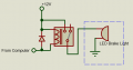
This is maybe one option:
 Ground trigger source would be from my bikes control unit (ECU/ECM/DME)
My number one goal is something that has no chance of damaging my bikes control unit or disrupting the function of my primary brake light.
My thoughts are that there is a way to just tap into (-s) on my schematic and use it as a ground trigger source without the possibility of putting any stray voltage into that line that could cause damage.
Is there a smaller/modern/safer/more reliable solution than a standard automotive relay?
I have been studying MOSFIT and maybe that is a solution or maybe solid state relay?
Thank you very much if you made it this far and if there are details I should add or clarify im happy to do my best. I have a multi meter if any other values are required.
I hope this made sense.
Thanks again.
Weather is great and im just banging my head into the wall trying to get this figured out.

I would like to add 2 of these aftermarket LED 3 function indicator lights near my license plate in conjunction with retaining my main rear tail lights. The 3 functions are: TURN SIGNAL (12 V - 1.1 W) / TAIL LIGHT (12 V - 0.5 W) / BRAKE LIGHT (12 V - 0.9 W) The 4 leads are sealed, 1 shared ground and 3 for the individual functions. All very easy for me EXCEPT the brake light function requires a positive signal and I believe my brake signal from the bikes computer to the rear tail light is a ground signal. im hopeful that i can come up with a MOSFIT solution or solid state relay that doesn't risk damage to my bikes control unit.
I'm not even remotely close to knowledgeable on electronic circuits, but I believe the reason the manufacturer says it is incompatible is because the signal going to my sealed rear light cluster for the brake light is a ground signal rather than a 12v powered signal.
This is a crop of the circuit from the manufacturer of my bike (12) is tail light, 2 functions lamp and brake light.
With my lights on I used a circuit test probe to find the wire to terminate to and was surprised as the moment I tested (2)(-s) my brake light came on without applying brake but the test light did not light up. I assume I just gave it the ground it was looking for. (3)(+) is powered on with my head lamp as it supply's power to both functions of the tail lamp. (1)(-) is always grounded.
1 terminates at the other grounds that my license plate and blinkers do.
2 terminates at the bikes control unit
3 terminates at the positive line that also runs to the license plate light.
Plug to tail light
Sealed LED tail lamp, top row is lamp and bottom row is brakes.
I just spent the last couple hours watching videos on MOSFIT's and relays used to convert a ground signal to positive signal.
This is maybe one option:
Ground trigger source would be from my bikes control unit (ECU/ECM/DME)My number one goal is something that has no chance of damaging my bikes control unit or disrupting the function of my primary brake light.
My thoughts are that there is a way to just tap into (-s) on my schematic and use it as a ground trigger source without the possibility of putting any stray voltage into that line that could cause damage.
Is there a smaller/modern/safer/more reliable solution than a standard automotive relay?
I have been studying MOSFIT and maybe that is a solution or maybe solid state relay?
Thank you very much if you made it this far and if there are details I should add or clarify im happy to do my best. I have a multi meter if any other values are required.
I hope this made sense.
Thanks again.
Weather is great and im just banging my head into the wall trying to get this figured out.
Last edited: