Advice for LED flasher circuit

Thread Starter

Tucks88

Joined May 20, 2025
14
Hello,

I'm quite new here and to circuit design in general, I'm usually repairing electronics & electricals but not designing them.
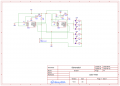
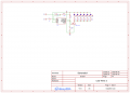
I'm trying to get some advice on making an array of 6 white LEDs with a Vf of 3v flash (ideally all out of sync).


The background is my kid bought a toy with his pocket money, it's a thanos infinity gauntlet but only one of the 'stones' lights up by design, when you press the stone an LED behind it lights up, some sounds play and the LED flickers on and off for about 16 seconds. He's super disappointed with it because in the films all the stones light up.

So I'm trying to find a way to light up the other stones, I've got some spare white LEDs with a Vf of 3v laying around and the batteries for the gauntlet are 2x AAA 1.5v cells.

The circuit inside the toy is very basic, with an IC that is a COB so I cant ID it, it looks for a signal from one of two switches and when it senses the signal it plays a random sound and flickers the LED.

I'm wondering if I can piggypack that signal and use it to activate a simple circuit for flashing/pulsing the white LEDs I have, usually I'd just wire the additional LEDs in parallel to the existing one but the one in place only uses between 1 and 2.5v which isnt enough for the LEDs I have.

Is there a way I can make a separate circuit for the additional LEDs, drawing power from the batteries directly and use either the signal from one of the buttons or the supply to the existing LED to activate a circuit that will flash the LEDs for about 15 seconds before turning them off until the next time?

Really sorry for the incoherent post, I'm not sure how to explain what I'm trying to do, but I appreciate any help anyone might be able to offer.
 

Jon Chandler

Joined Jun 12, 2008
1,572
The very easiest way to do this is with self flashing LEDs. Connect power and they flash. They are rated for flashing at the same frequency, but there's enough difference in frequency between LEDs that they quickly assume a random pattern. Tayda Electronics at the link above has them in white and a number of other colors.

Screenshot_20250520_131011_Edge.jpg
 
Last edited by a moderator:

Thread Starter

Tucks88

Joined May 20, 2025
14
The very easiest way to do this is with self flashing LEDs. Connect power and they flash. They are rated for flashing at the same frequency, but there's enough difference in frequency between LEDs that they quickly assume a random pattern. Tayda Electronics at the link above has them in white and a number of other colors.
Hi Jon, thanks for the reply.


These still have a forward voltage of 3v, meaning they would need to be driven directly from the batteries in the device. I'd still need some way of activating them using the switch (it's one of those silicone membrane switches with the conductive traces)else they would constantly be flashing, or only flash for a moment as the button was pressed to complete the circuit.

Is there any way I could use a 555 timer or similar to activate the LEDs using the silicone membrane switch? From searching I cant seem to find that 555 that activates at <5v.
 

seanstevens

Joined Sep 22, 2009
323
White LEDs will require 3V and higher, while red LEDs can do with around 2.6V or less on some. As for the 555 timer circuit, I think you may need a re-triggerable 555 timer circuit. Here is the Google search page. Also, try clicking on the images (top), which will show you a rough idea of the circuit.

Depending on the activation switch polarity signal you have in the toy, you may need to invert the signal at the input of the 555. If you use 7555, the CMOS version, it uses much less power, but keep an eye on the final output current of the 7555, exceed it and it will die. You may need to use a buffer transistor if your current is too high for it. Good luck.
 

Thread Starter

Tucks88

Joined May 20, 2025
14
White LEDs will require 3V and higher, while red LEDs can do with around 2.6V or less on some. As for the 555 timer circuit, I think you may need a re-triggerable 555 timer circuit. Here is the Google search page. Also, try clicking on the images (top), which will show you a rough idea of the circuit.

Depending on the activation switch polarity signal you have in the toy, you may need to invert the signal at the input of the 555. If you use 7555, the CMOS version, it uses much less power, but keep an eye on the final output current of the 7555, exceed it and it will die. You may need to use a buffer transistor if your current is too high for it. Good luck.
Sean, thank you so much for the information! I'm sure I can find something in there I can work with and start drawing up a schematic.
 

Thread Starter

Tucks88

Joined May 20, 2025
14
So after messing around for a while, I figured stable light output would be fine for a defined time (approx 16s) after a button press.

I went with trying to make a monostable circuit with two 7555ICs using the same trigger. Two ICs because the max output on one is 100mA and there are 6 LEDs at ~20mA each. Split the load across two to keep them well under their absolute maximum ratings.

I'd made a schematic, put it into TinkerCAD circuit deisgn, it worked.

I then copied that over to EasyEDA and ordered the PCB but, sadly, it doesnt seem to work.

Here's the schematic form EasyEDA,can someone have a look and tell me if I've made a mistake? I have a few PCBs spare now so I can always pull components from the boards and use a perfboard or something to prototype.

Apologies if this looks horrendous to you guys, it's the first time I've designed a PCB and made a schematic for electronics (done and use electrical for work, but thats a whole different kettle of fish!)

Thanks
 

Attachments

Last edited:

Irving

Joined Jan 30, 2016
5,066
120mA from 2 x AAA for 16sec... how many button presses do you think they'll last (typical alkaline AAA = 1000mAH)? That's why the toy only had one LED....
 

Thread Starter

Tucks88

Joined May 20, 2025
14
One 7555 circuit with a mosfet can drive all 6 LEDs at 20ma each.
View attachment 350917
Thats considerably neater than my attempt, thank you.


120mA from 2 x AAA for 16sec... how many button presses do you think they'll last (typical alkaline AAA = 1000mAH)? That's why the toy only had one LED....
I thik it should be fine, I'm using 900mAH rechargeables, so a bit less than standard non rechargeable cells. The current circuit uses around 35mA, so 155mA total if I added the extra lights, excluding losses from any IC or a MOSFET, for arguments sake lets say it's 15mA on losses but I'd imagine it'll be a bit less.

900mAH / 170mA = 5.294 Hours or 19058 Seconds (approximate)

If each cycle is about 16 seconds (lets say 17 as I think it's slightly over 16) that's around 1121 uses before the battery is dead.

If it gets even 30% of that usage before needing to recharge I'd be happy with it, the noise would have likely driven me insane by that time anyway.

Sadly I think the real reason it has one light is cost saving on production, lighting the other parts requires more manufacturing steps and components.
 

ci139

Joined Jul 11, 2016
1,976
a thanos infinity gauntlet
https://www.google.com/search?clien...AIHWorOY0Q0pQJegQIEhAB&biw=1280&bih=899&dpr=1

the AAA-s differ by manufacturer and the by the cell type/chemistry -- usually you shouldn't expect more than some ::
  • 1A * capacity AAA(RL03) / capacity D(RL20)
  • 1A * √¯volume AAA / volume D¯'
— of operation (heavy discharge) pass the 30 minutes ≈ . . .

D-type (46cm³)2000÷6900mA·h
AAA (3.3cm³)860÷1200mA·h

. . . ≈ 273mA @ short circuit . . . however -- the led-s likely won' t qualifiy for a heavy load (unless you want them be visible at direct sunlight . . .)

the easiest approach would be multiplex LED-s with mosfets using original terminals ??? -- but it takes testing if such is implementable and if it has satisfactory luminance ??
 
Last edited:

sghioto

Joined Dec 31, 2017
8,634
Nickel metal hydride - Duracell branded
That might be a problem as a fully charged cell is appx 1.35 volts but will quickly discharge to 1.25 volts.
May not be enough to illuminate the LEDs or activate the mosfet Q1.
Have you considered using a single cell lithium rechargeable ?
Either a Li- ion at 3.7 volts or a LiFePO4 at 3.2 volts
v
 
Last edited:

Irving

Joined Jan 30, 2016
5,066
That might be a problem as a fully charged cell is appx 1.35 volts but will quicly discharge to 1.25 volts.
May not be enough to illuminate the LEDs or activate the mosfet Q1.
Have you considered using a single cell lithium rechargeable ?
Either a Li- ion at 3.7 volts or a LiFePO4 at 3.2 volts
I use these, both in AAA and AA format, Lipo rechargable with internal buck converter to 1.5v. Rock solid 1.5v until exhausted then they turn off. AA have internal charger, but AAA need external one
 

Thread Starter

Tucks88

Joined May 20, 2025
14
It seems you can get the AAA lipo with internal charger too now:

Thats quite impressive to fit a charging crcuit, presumably with a BMS and not lose much capacity at all.

I'll have to look into these and slowly replace my collection of older rechargables, thank you :)


That might be a problem as a fully charged cell is appx 1.35 volts but will quickly discharge to 1.25 volts.
May not be enough to illuminate the LEDs or activate the mosfet Q1.
Have you considered using a single cell lithium rechargeable ?
Either a Li- ion at 3.7 volts or a LiFePO4 at 3.2 volts
v
I'd not thought of that to be honest, it's a very valid point.

Just for the sake of it Ihave tried some standard alkaline batteries (new Varta) and they didnt provide enough power through the circuit already in the toy to drive any of the LEDs I have apart from dim red and green LEDs, but they're not noticable when in the toy.

I'm either going to go down the lipo/lifepo route or disposable alkaline when it's up and running, I'm leaning towards the ones @Irvinghas posted as I don't like the idea of a pouch style cell in there while it's being bashed around.
 

Thread Starter

Tucks88

Joined May 20, 2025
14
Hello again!

Another weekend, another attempt (and subsequent failure) to finish this little project, it has become more about getting it working for my sake now rather than anything else.

I've built the circuit that is in the attached schematic and it works! But then it doesnt.
After powering the circuit on and triggering it with the switch, it does exactly what I need, powers the LEDs for about 12 seconds (guessing the difference in tolerances for components have dropped it from 16s to 12, not a problem)then they turn off.

Problem is I can only trigger it once, then it wont trigger again, all it does is light the LEDs whilst the switch is pushed down.

Assuming it was an issue with the capacitor I pulled C2 down to ground with a jumper lead to ensure it was discharged, then when hitting the switch again it works as expected, for 12 seconds, once. It then continues to act as above where until I drain C2 to ground it wont keep the LEDs on unless the switch is pushed and held down.

Do I have an issue with the design? I've tried 3 capacitors (electrolytic and tantalum) now, to no avail. I've switched out the 7555 for one of the others I have, same issue. Resistors are very close to their expected resistance (within 5%) so I'm a bit stumped, why would it work once then not work until C2 is fully discharged?

I've attached the PCB layouts too, but they should be okay as they follow the schematic and I auto routed them (I know I shouldnt rely on that, only found out recently that it's not ideal for learning)

Top Layer:
1751205083656.png

Bottom Layer:
1751205134190.png

Again, thank you all for you help so far, it has been invaluable.
 

Attachments

Last edited:
Top