Downsizing a signal

Thread Starter

E.H

Joined Aug 13, 2020
1
Hi,
I'm new here.
I have a problem hoping to get a solution here
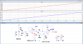
I have to measure a analog signal in the range of -10v to +10v.
My A/D can measure only 0-2.5V
How can I downsize the signal and raise the dc level so that the A/D can read it?
I am aware that this is not the best solution as I loose resolution but I am limited to the A/D
 

ericgibbs

Joined Jan 29, 2010
21,439
hi EH,
Welcome to AAC.
It can be done using say a couple of OPA's.
E

Update:
Use a second OPA to provide the -1.25Vref.
Added a Vref option.
Capture.PNG
 

Attachments

Last edited:

ci139

Joined Jul 11, 2016
1,989
proper pull up/dn resistive divider to either Vdd or +2.5V ( or whatever is the reference/supply for your ADC )
http://tinyurl.com/y27759a8 (it does a linear conversion http://tinyurl.com/y3v5rhxt in theory)
for a success it requires the +5V to be regulated (to have a near Const. value)
about
\[\cases{R_S=R_L+R_H\ --\ the\ lowwermost\ potentiometer\\V_{GND}=0}\\V_X=\frac{R_L}{R_S}·\frac{V_{IN}R_{REF}R_{S}+V_{REF}R_{IN}R_{S}+V_{GND}R_{IN}R_{REF}}{R_{REF}R_{S}+R_{IN}R_{S}+R_{IN}R_{REF}}\]
from :
\[\cases{\mathbf{V_{XS}}=V_X\frac{R_S}{R_L}=2.5V·2=5V\ ,\ \text{if}\ R_L=R_H=\frac{R_S}2=1k\Omega\ , \text{see below}\\\Delta V_{XS}·\Sigma R=\Delta V_{IN}R_{REF}R_S\\V_{XS_{Lo}}=0\ \rightarrow\ V_{IN_{Lo}}R_{REF}+V_{REF}R_{IN}=0}\]
we get :
\[\frac{R_{IN}}{R_{REF}}=\frac{-V_{IN_{Lo}}}{V_{REF}}\]
and if the \(R_S\) is set (say \(R_S=2k\Omega\)) , then :
\[\cases{R_{IN}=R_S\left({\frac{\Delta V_{IN}}{\Delta \mathbf{V_{XS}}}-1+\frac{V_{IN_{Lo}}}{V_{REF}}}\right)=2k\Omega\left({\frac{10V-(-10V)}{5V}-1+\frac{-10V}{5V}}\right)=2k\Omega\\R_{REF}=R_{IN}\frac{V_{REF}}{-V_{IN_{Lo}}}=2k\Omega\frac{5V}{-(-10V)}=1k\Omega}\]
the first simulation with derived values : http://tinyurl.com/y4c2454h
ADC V scaling.png
 
Last edited:

ericgibbs

Joined Jan 29, 2010
21,439
hi C,
The TS has not stated he has a -1.25Vref available for the project.

Note:
The first LTS circuit I posted shows a simulated -1.25Vref connected directly R3.

The second LTS circuit shows the TS how to create a -1.25Vref, using a OPA buffer to drive R3.

The circuit will work equally well in this application with either 1k or 10k resistors.

If you have a preference for 10k's, I don't have a problem.

E
 
Last edited:

crutschow

Joined Mar 14, 2008
38,504
Below is an example circuit of what I meant by eliminating the buffer opamp with a 2.5V reference, using the common TL431 2.5V reference voltage IC.

My preference for higher resistor values in this application is that it minimizes supply current and loading without significantly affecting circuit function.

1597367529056.png
 
Last edited:

ci139

Joined Jul 11, 2016
1,989
just a note - the TL431 "unbiased"/"raw" shunting voltage can vary from 1.8 to 2.8 V -- it is fixed for a particular instance , but is varying from instance to instance
 

DickCappels

Joined Aug 21, 2008
10,661
The TL431 still has its feedback connected. It just looks funny because we are accustomed to seeing it flipped vertically from the way it is shown. Why would the voltage vary as long as the required cathode current is maintained?
 

crutschow

Joined Mar 14, 2008
38,504
TL431 "unbiased"/"raw" shunting voltage can vary from 1.8 to 2.8 V
Why unbiased?
The TL431 has the sense terminal connected to the cathode, and is biased by a negative voltage through R6, which will give a nominal negative voltage across it of 2.5V
 

ci139

Joined Jul 11, 2016
1,989
i apologize using an opaque terminology - what i meant by "unbiased" is exactly that the Reference is shorted to Cathode
 

crutschow

Joined Mar 14, 2008
38,504
...what i meant by "unbiased" is exactly that the Reference is shorted to Cathode
The Reference input connected to the cathode is the normal configuration for a nominal 2.5V output from the TL431.
That is not an "unbiased" condition.
 
Last edited:
Top