Door lock reminder

Thread Starter

Sergio34

Joined Nov 10, 2018
52
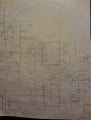
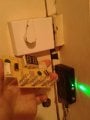
As I have been helped a lot from other members' answers as a courtesy I want to give something back. I am relatively new to the hobby, maybe someone at the same level will find it (or parts from it) useful. We have a door that we keep forgetting to lock. Not anymore, this design will flash LEDS and after sometime will sound a buzzer. This is finished now and works fine, this doesn't mean the circuit is optimal. The switch on the right will stay pressed as long as the door is unlocked. The 555 timers will flash the red & yellow LEDs alternatively with the green one and after a while the buzzer will sound. How much time after depends on the trimmer pot position, somewhere between 30' to 3 mins. When door is locked the green LED is on all the time. Actually I did not plan initially the green LED to be permanently on but it happened accidentally and I liked it as it gives a high tech tone to the house. There are times that the door needs to be unlocked for some time when going constantly in and out doing errands for example, so the DPDT switch comes in to play. When it is on the other position the LEDs flash continuously either the door is locked or not, but with no sound. The LEDs will remind to put the switch back when finishing the errands. I posted recently parts of the circuit asking questions. I know now that some parts like that PNP transistor are not necessary, but it is too late now. You may find other parts that are not needed... But I insist on that MPS A13 transistor, as the area in the lock is confined a I had to make a DIY switch with a spring and a small piece of metal, so the conductivity is questionable. Please ask if something is not clear.
 

Attachments

Last edited:

dl324

Joined Mar 30, 2015
16,846
Thank you for your contribution.

Your description would be easier to read if you used paragraphs to organize and your circuit diagram would be easier to read if you didn't use that "wiring diagram" style.

I'll redraw your schematic shortly to illustrate.
 

Thread Starter

Sergio34

Joined Nov 10, 2018
52
the interesting part here would be the door locked sensor
? brake switch inside what
I did not do anything in the lock mechanism, whatever I did is in the case (part 16 from your drawing). The PCB in the first photo was from a faulty dehumidifier I broke. The springs used to be touch buttons. The corner that is missing went into the case of the lock and on the left there is a small metal piece that is touched from the spring when unlocked which is closing the circuit.
 

Attachments

dl324

Joined Mar 30, 2015
16,846
For what it's worth, this is what I transposed:
clipimage.jpg

Timer IC2 doesn't make sense to me. Why do you have 3 resistors? What is the purpose of D3? You never discharge C4, so D3 does nothing.
 

Thread Starter

Sergio34

Joined Nov 10, 2018
52
Thanks for your suggestion, so it makes sense because you understood it but I guess you mean it is not the professional way to draw. I will re draw next time the circuit more clearly, it was the first time and I was looking forward to let some steam out by posting something.
 

Thread Starter

Sergio34

Joined Nov 10, 2018
52
For what it's worth, this is what I transposed:
View attachment 194906

Timer IC2 doesn't make sense to me. Why do you have 3 resistors? What is the purpose of D3? You never discharge C4, so D3 does nothing.
Wow! what software do you use to draw this? IC2 causes the delay for the buzzer so it does not sound immediately. 555 timer is in delay on (and stay on) mode. A few weeks ago I posted a question about 555 timer's strange behaviour, you can see the post here:
https://forum.allaboutcircuits.com/...ore-on-strange-behaviour.165052/#post-1453271
The problem was that it could not do the task properly and we discovered that with supply voltage above 5V indeed it doesn't (this problem is in regard to that specific delay on mode only). Somebody posted a very helpful answer with the extra resistor and diode at threshold pin. Something about parasitic current which I am not sure I understood. By the way you made at least one error in the schematic. The D3 and C4 are not in the correct position. Only 15K resistor and connection to trigger leave from Threshold pin. So D3 helps C4 to discharge.
 

dl324

Joined Mar 30, 2015
16,846
By the way you made at least one error in the schematic. The D3 and C4 are not in the correct position. Only 15K resistor and connection to trigger leave from Threshold pin. So D3 helps C4 to discharge.
Corrected wiring around R10:
clipimage.jpg

It still doesn't make sense. C4 won't discharge as long as power is applied to the circuit. D3 is always reverse biased, so it does nothing. If you used the discharge pin, it would shorten the discharge time.

Wow! what software do you use to draw this?
I use an old free version of Eagle (V4.13r1). The 555 timer component is customized because the standard component was retarded.
 

dl324

Joined Mar 30, 2015
16,846
Hopefully, the final revision. I corrected the value of R4 and added the value for the pot.
clipimage.jpg

When power is first applied, C4 pulls the threshold pin of IC2 to 12V. When THR is above 0.67Vcc, the timer output is set to LOW. C4 now charges through R11 and R12. When the voltage across the cap gets to 0.67Vcc, the timer output goes HIGH and stays high until power is removed.

R10 does nothing because it’s in series with high impedance comparator inputs.

D3 does nothing because it’s reverse biased as soon as C4 starts charging.


I still don't understand what S2 and Q3 do.

If the door is unlocked, S2 is closed. That does nothing because Q3 can't be turned on. When S1 is in the normal position, half of it connects the emitter of Q3 to 12V (which does nothing). When S1 is in the other position, it does nothing but connect the switch contacts which are both at 12V.
 
Last edited:

Thread Starter

Sergio34

Joined Nov 10, 2018
52
Hopefully, the final revision. I corrected the value of R4 and added the value for the pot.
View attachment 194913

When power is first applied, C4 pulls the threshold pin of IC2 to 12V. When THR is above 0.67Vcc, the timer output is set to LOW. C4 now charges through R11 and R12. When the voltage across the cap gets to 0.67Vcc, the timer output goes HIGH and stays high until power is removed.

R10 does nothing because it’s in series with high impedance comparator inputs.

D3 does nothing because it’s reverse biased as soon as C4 starts charging.


I still don't understand what S2 and Q3 do.

If the door is unlocked, S2 is closed. That does nothing because Q3 can't be turned on. When S1 is in the normal position, half of it connects the emitter of Q3 to 12V (which does nothing). When S1 is in the other position, it does nothing but connect the switch contacts which are both at 12V.
There are a lot of errors in your redrawing which tells me you did not observe it carefully and that’s why you do not understand it. In fact it is very messy, this is not what I designed. Maybe I should redraw it when I learn to use that software.

ERRORS:

These components must connect all together ONLY to the position 5 of S1 (one of two common poles of DPDT switch), not to the 12V rail:
V+ & RESET pins of both ICs, R6, C5, C6

Line from position 5 of S1 to 12V rail should be erased.

C6 & C5 should be clearly very close to V+ and GND pins of the ICs.

There is a line B1,B under R7 which does not make sense.

Please correct these above and you can continue reading.

S2 closes the circuit (makes contact) when door is unlocked. That turns on Q3 very well. It is not 2N3904 but an MPS A13 (Darlington) transistor which has high gain but any transistor would be turned on, why you say it cannot be turned on?

S1 at normal position connects the Q3 with the ICs. This is so they start only when door is unlocked. If S1 is on the other position then the ICs are turned on either door is unlocked or not since they are connected directly to supply voltage. The other half of the S1 at normal position connects output of delay IC to the Q2. This way the buzzer will sound after a while. In the other position S1 connects base of Q2 to GND so it turns off.


The whole point of S1 is when door is intentionally unlocked for long time sound is off so it is not annoying but there is visual reminder (LEDS) to put the switch back to normal. This is a reminding device after all and must do "reminding" very well. This is how I chose it to do.

D3 helps to discharge C4 quickly, otherwise it would have to discharge very slowly through 470K and 2.5M resistor. This in practice means delay IC is ready to start its cycle (delay) again even after door is locked momentary and unlocked again.

There is something I cannot answer, and that’s the use of R10 but you may go and ask the member who suggested that in the older thread I told you above, the thread is still fresh, is not that old. You will find your answer there and it may help me to understand too. All I know is that there were problems without it. It has to do with 555 in “delay on” mode with supply voltage above 5V. (In the past I managed to do "delay on" with 555 timer successfully using the CMOS version which works from 2V and use of that awkward 15K resistor was not on the table).

The area around the green LED is understood now that has some unnecessary components, like the PNP transistor. Also the 3.9K resistor maybe is unnecessary for some. I was struggling to turn the green LED fully off so this is what I did.
 

Thread Starter

Sergio34

Joined Nov 10, 2018
52
It seems that this works too :)

I made some changes so green led is on when standby
http://tinyurl.com/telskx6
http://tinyurl.com/umttp4b . . . quite an "angry" circuit F;·i (hi-hi)
My bad the previous version, here is actually what I made (I hope... finally). I repeat it doesn't mean is perfect but it does what I wanted it to do. Changes include also an incorrect connection you had at the DPDT switch at the top.
http://tinyurl.com/qkb2zer
 
Last edited:

ci139

Joined Jul 11, 2016
1,898
you found a practical solution to a household problem ✔
you actually built and installed it ✔
____

i usually cancel freeze my projects at any pre-test that hints complexity rise or the need for costly , tiny footprint or otherwise inconvenient to use components or simply the components that i already don't have in my drawer

things don't have to be over perfect - if they do their job

. . . i've found it more practical to have a set of resistors than a fancy Lab Supply that definitely will not have a range or tuning precision at some point . . .
 

Thread Starter

Sergio34

Joined Nov 10, 2018
52
you found a practical solution to a household problem ✔
you actually built and installed it ✔
____

i usually cancel freeze my projects at any pre-test that hints complexity rise or the need for costly , tiny footprint or otherwise inconvenient to use components or simply the components that i already don't have in my drawer

things don't have to be over perfect - if they do their job

. . . i've found it more practical to have a set of resistors than a fancy Lab Supply that definitely will not have a range or tuning precision at some point . . .
I forgot to say thanks for the time you took to build this in Falstad. Intrigued I spent all morning learning to use it and is so much fun and helpful.
 
Top