Request: 4-Digit Digital Door Lock Circuit Schematic

Thread Starter

Leon_V_G

Joined Oct 26, 2025
4
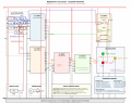
I'm looking to generate a schematic for a logic-based 4-digit digital door lock circuit using CMOS logic ICs and LEDs, powered by a 5V DC adapter.

System Overview
  • 4-digit password entry via 10 tactile push buttons (0–9 keypad).
  • Each correct digit advances a CD4017 counter (code sequencer).
  • Wrong key press resets the sequence.
  • After 3 wrong attempts, 1-minute lockout triggers, disabling keypad input.
  • Red LED ("locked"), green LED ("unlocked"), yellow LED blinks during lockout.
  • System resets on power-off.
  • Power: regulated +5V DC.
ICs and Roles
  • U1: CD4017 Decade Counter (Code Sequencer)
  • U2: CD4017 Decade Counter (Attempt Counter)
  • U3: NE555 (Lockout Timer, ~60s duration)
  • U4: CD4013 (Lockout Latch)
  • U5: CD4011 (Quad NAND Gate, used for logic/reset)
Components
  • Diodes: 1N4148 ×6
  • Resistors: 5.5 MΩ (555 timing), 100 kΩ ×6 (button pull-downs), 10 kΩ ×2 (biasing), 1 kΩ ×3 (LED current)
  • Capacitors: 10 µF (555 timing), 0.1 µF ×5 (decoupling), 0.01 µF (555 control pin)
  • LEDs: red, green, yellow
  • Keypad: 10 push buttons
  • 1 reset push button
Expected Operation
  • Starts locked (red LED ON).
  • Correct 4-digit entry → green LED ON (unlocked).
  • Wrong key resets sequence.
  • Three wrong attempts → lockout, yellow LED blinks (~60s).
  • Timer expiry resets lockout; red LED ON.
I am seeking a clean, classic schematic in engineering style—with clear IC rectangles, pin numbers, organized wiring, and all described components visible. Any SVG/tool-generated examples or advice for making the schematic easier to read would be appreciated. Thank you!

You can have the attached circuit as a reference. Appreciate the help
 

Attachments

ericgibbs

Joined Jan 29, 2010
21,390
Hi Leon
Welcome to AAC.
As this appears to be a College assignment, please post your best attempt at answering with an operating explanation

Moderation.
 

Thread Starter

Leon_V_G

Joined Oct 26, 2025
4
Hi Leon
Welcome to AAC.
As this appears to be a College assignment, please post your best attempt at answering with an operating explanation

Moderation.
  • The circuit starts in the “locked” state, showing the red LED.
  • Entering the Code: When the user presses the correct sequence of 4 keys on the keypad, a counter (CD4017) advances step by step, activating the green LED when all 4 are entered in order.
  • Wrong Input: Pressing any incorrect key resets the sequence, requiring the user to start over.
  • Lockout Feature: After 3 consecutive wrong attempts, a second CD4017 triggers a NE555 timer, locking out keypad input for 60 seconds while the yellow LED blinks; after the timer expires, the circuit resets to “locked”.
  • Reset: All counters and indicators reset automatically if power is cycled or when the manual reset button is pressed.
  • LEDs: Always indicate status—red for locked, green for unlocked, yellow for lockout.
 

Thread Starter

Leon_V_G

Joined Oct 26, 2025
4
Those are merely the requirements of the project. What proposals do you have for fulfilling them?
I'm actually new to circuit design and working on this as a college project. My initial proposal is to use a CD4017 decade counter as a sequencer for the correct code, another CD4017 for counting the number of incorrect attempts, a NE555 timer for the lockout timing, and some standard logic gates like CD4011 and a CD4013 flip-flop for control logic and output latching. I’d appreciate any feedback or suggestions for a more robust approach, as my experience so far is mostly at the beginner level.
 

Thread Starter

Leon_V_G

Joined Oct 26, 2025
4
Welcome to AAC!

What is the source of this wiring guide? It looks like a workable starting point for your circuit.
Since I’m still fairly new to building circuits, I used an AI-based schematic assistant to help generate a reference design after researching similar projects online. I’m not sure if it’s directly from a textbook or a particular website, so I posted here to get advice from experienced members and to make sure the approach is reliable for my college project.
 

dl324

Joined Mar 30, 2015
18,219
I used an AI-based schematic assistant to help generate a reference design
AI is currently unable to design circuits because schematics and circuits aren't typically represented in words that can be used to train them. As a schematic, it's drawn terribly.
I posted here to get advice from experienced members and to make sure the approach is reliable for my college project
That isn't how homework help works. You need to show your best effort so we can offer hints when you get stuck.
 
Top