Facebook
 Google
 GitHub
 Linkedin
I am currently working on an upgrade to my door security system and I'm seeking advice on how to properly wire a circuit with multiple control points. The system involves an electric door lock that operates on a 12V input. Here's the setup:
My questions for the community are:
Thank you in advance for your expertise!
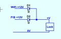
- The primary control is a Wi-Fi-enabled doorbell that, when activated, sends a 12V signal to unlock the door.
- I wish to integrate an additional manual exit button that, when pressed, also sends a 12V signal to the same electric lock to allow exit from inside without interacting with the Wi-Fi doorbell system. i can use another 12v adapter or 12v battery
My questions for the community are:
- What is the correct term for this type of circuit configuration with multiple inputs controlling a single load?
- Can someone provide guidance or a schematic on how to wire two 12V inputs in parallel to control one electric door lock?
- Are there any specific considerations or components I should include to protect the circuit from potential backfeed or voltage spikes?
Thank you in advance for your expertise!