Trying to understand series / parallel wiring of multiple COB LEDs in lighting fixture

Thread Starter

LeeMiller

Joined Nov 17, 2024
3
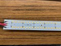
I was trying to troubleshoot a failed LED lighting fixture and got caught up trying to understand how the LEDs are wired. I'm guessing there must be four series LEDs in each of a bunch of parallel circuits, each with a 39 ohm current limit resistor. LED+ is connected to the lower contact of all the upper resistors and + is connected to the upper contact of the lower set (labeling seems oddly asymmetrical). - and LED- are not connected to anything I can measure, but I can't get to the surface mount contacts of the LEDs themselves. Are two of the leads sensing current or something? I assume this is a standard enough circuit that someone out there will easily recognize it. At this point, it is idle curiosity, but it is beginning to bug me…
 

Attachments

panic mode

Joined Oct 10, 2011
4,864
i don't see why it is hard to follow traces or probe with DMM... at least zoom in...
from what i see repeating pattern is that R is connected to (+), then D1/D2 (in parallel) and then D3/D4 (in parallel) then (-).
so assuming those are conventional LEDs rated for max 150mA with Vf of 3.1V and operated at lower current (some 50mA), each resistor is passing some 100mA and have voltage drop about 4V. so this strip would be meant for maybe 9..10V.

1731871789393.png
1731872084455.png
 
Last edited:

Thread Starter

LeeMiller

Joined Nov 17, 2024
3
Duh! I hadn't even bothered to look at the picture I uploaded. The traces are much more obvious in it than my attempts to look at the circuit board from various angles! So the two minus leads, and the 2 plus leads are simply supply and return, with different labels? Next, a design question. Why not a smaller resistor and lower supply voltage to dissipate less power? I realized, after sending, that they power one or both circuits to control two light levels...
 

MisterBill2

Joined Jan 23, 2018
27,159
The supply voltage is mostly a matter of convenience, unless maximum efficiency is a major issue. I would have guessed strings of four in series with a resistor instead of two sets of two in parallel in series with two more. A pair of probes with needle points will allow probing the solder connections at the LEDs and learning the actual connections. If all of the LEDs do not have to be exactly the same brightness and color than many can be connected in parallel, and the parallel arrays connected in series, with one current regulator for a large number of LEDs. I disassenbled one massive parking lot light with at least seven banks of 28 parallel connected LEDs, all the banks in series, and one current regulator circuit.Three or four of those 28 LED banks in series with one resistor will produce a huge amount of light, using a 12 volt DC supply. But they will certainly need a serious heat sink.
 

Thread Starter

LeeMiller

Joined Nov 17, 2024
3
This was a solar powered light, so I would have thought high efficiency would have been a priority. Perhaps 4 diodes in series required a higher supply voltage than they cared to produce.
 

MisterBill2

Joined Jan 23, 2018
27,159
In the design of consumer items, especially low cost ones, efficiency is toward the last item in priority. Using the available voltage often requires a compromise.
 
Top