Documenting a TRF Radio build

sparky 1

Joined Nov 3, 2018
1,218
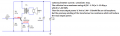
Some headphones used for hearing protection to muffle the sound of shot gun. I use these for the small speaker enclosures.
I would like to find better speakers, I suspect the aircraft variety without the noise cancelling would have the Q and response for the vocal audio range needed to articulate talk and other signals. The audio amplifier circuit for simple radio might be made of discrete components when it accomplishes better radio readability of weak signals. A note relating similarity with music and radio design criteria.
I think radio builders of past needed to develop an ear. I find it curious that the ears of musical quality artists have acquired excellent finite skills in distinguishing sounds of the musical scale which are also by nature exponential. Because exponential is nonlinear a think an audio voltmeter would be very helpful when used properly would be more objective.

Many times we adjust the volume as we change station the signal reception is different so both audio amplification and preamplifier gain are tied together so eventually both gains work together.

A note about TRF: Tuned Radio Frequency architecture can be considered a departure from crystal radio but it is not.
As radio improved TRF grew. Crystal radio remains committed to the preservation of early models and is by right puritanical in that regard.
My experience with the puritans is they refuse to allow any improvement within their society guidelines however some of their
replications have nice spider coils and valuable collections, useful data you will find they tend reject most TRF projects and oppose any suggestion about the less popular crystal radios that do not fit their legacy.
 
Last edited:

Thread Starter

Anonymous User 30

Joined Sep 4, 2017
40
Thank you for all your replies.

I think this is the direction to go in:

1. Redesign the amplifier in line with Audioguru and Mr Chips ideas.
2. Make use of an audio transformer to reduce signal loss.

Mr Chips - I will hold off on the push pull amplifier just yet as I have to study it, learn its workings etc. I appreciate the design nonetheless.

I am going to redesign the amplifier with audiguru's ideas and utilise an audio transformer as suggested by Mr. Chips.
 

Thread Starter

Anonymous User 30

Joined Sep 4, 2017
40
Just a few questions regarding the amplifier:

1. RL was added in the first stage to alter the output impedance of the first stage. I must take this in consideration when designed the biasing resistors as well as RE for the second stage? As audioguru suggested we do not match impedances but strive to preserve signal.

2. Is there anything reason utilising a step down audio transformer to drive the 4Ohm speaker I have will not work for whatever reason? (Zp / Zs = (Np/Ns)^2)

3. 22R Rc resistor is viewed as an attenuator. If it is removed wont the current too excessive for the 6W rms speaker? The battery I plan to use with the radio is a 12V 2.3Ah battery.
 
Last edited:

Audioguru again

Joined Oct 21, 2019
6,826
RL was added to the 1st stage because it represents the load presented by the biasing resistors and transistor of the second stage.
You used a collector resistor value of 680 ohms which produced low voltage gain and was overloaded by the RL of 200 ohms of your second stage.

I used a collector resistor value of 2.2k and an RL of 22k for lots of voltage gain and no overloading. The gain was high enough to add negative feedback for low distortion.

Old vacuum tube amplifiers used an output transformer to allow an 8 ohm speaker to be driven from the 100VAC at 10k ohms of a vacuum tube to produce 1W at 4 ohms. You do not have 100V so a transformer will simply reduce your 3.5VAC and reduce the output power. Most transistor amplifiers do not use an output transformer.

Your circuit without the 22 ohms resistor is class-A and has 6VDC in the speaker all the time. Its current is 6V/4 ohms= 1.5A (9W of heat) which might destroy the speaker and it holds its cone over to one side causing severe distortion. A push-pull amplifier uses class-AB for a fairly low idle current and no DC in the speaker, but lots of output power when it is loud.

A modern amplifier has a "bridged" output that has two amplifiers, one amplifier for each speaker wire so that the speaker gets double the voltage swing for almost 4 times the power of a single amplifier.
 

Attachments

Thread Starter

Anonymous User 30

Joined Sep 4, 2017
40
Thanks Mr Chips, really appreciate your help!

I'll try that circuit and report back, I just need to source the transistor.

Once I have completed the circuit I'll report back, and then I will try to add another stage for selectivity.
 

Thread Starter

Anonymous User 30

Joined Sep 4, 2017
40
Mr Chips, im interested in how the output impedance of the amplifier is calculated for your circuit. Would it be input impedance (as defined by the datasheet) divided by the Hfe (DC current gain)?
 

sparky 1

Joined Nov 3, 2018
1,218
I ran a simulation on the last circuit it works good. Don't forget the 10uF next to R3.
A 32 Ohm speaker 6:1 excellent
The 16 Ohm speaker with 6:1 is very good
A 4 Ohm speaker with 15:1 is almost as good
I also tryed a BC849 had small difference.
Running at 12Vcc setting the audio frequency generator to 1kHz and 1 mV rms equals 364 mV rms out. 9V gave 243mV rms
The THD was under 0.15% the transformer ratio had the greatest effect on this circuits distortion. (maybe homemade transformer will improve it more)
If I have the simulation on the transformer right, it will work good as drawn so now just waiting mode.
 
Last edited:

MrChips

Joined Oct 2, 2009
34,829
Thanks Mr Chips, really appreciate your help!

I'll try that circuit and report back, I just need to source the transistor.

Once I have completed the circuit I'll report back, and then I will try to add another stage for selectivity.
I don’t pay particular attention to the part number of the transistor. I just use what I have in my collection.

I will show you how I improved the RF selectivity at the aerial stage.
 

MrChips

Joined Oct 2, 2009
34,829
This is what I have working on a breadboard now.

Selectivity is greatly improved by using a dual coil at the antenna. I have coils wrapped around two cardboard tubes of different diameters. One coil slides over the other. The secondary coil has about 100 turns or wire.

The signal from the long wire antenna was overloading the tuning circuit giving zero selectivity. Adding C7 in-series with the antenna solved the problem. Overall selectivity and volume output far exceeds my expectations.

There is too much gain in both AF driver and output stages. Hence I removed the decoupling capacitors that you would normally see across emitter resistors R6 and R10. The volume control is necessary in order to adjust for nearby and distant stations. I can pick out and select about 10 stations in my area.

Voltage supply V1 is a 12V battery which replaces the previous 9V battery.

Crystal Radio with AF transformer output.jpg
 

atferrari

Joined Jan 6, 2004
5,012
To the OP and all contributing: I do not intend to derail this thread at all. Once getting this answered I will vanish. Promise.

A couple of points that have intrigued me for a long time:

a) Why Germanium and not a silicone diode? Wouldn't it work at all or just marginally? Is it the Vf, the reason? If so, why not a Schottky?

If decided to use a silicone / Schottky diode, what could be the way even if expensive in terms of components to have it working? What diode could / should I try?

b) What could be the way to avoid a transformer in the audio amplifier even if expensive in terms of components to have it working?

Just in case, I am not interested on the "classic" aspect of these circuits.
 

MrChips

Joined Oct 2, 2009
34,829
a) Ge vs Si. The simple answer is Vf.
Ge has lower Vf. The "classic" crystal radio calls for a cat's whiskers point-contact crystal diode which I used when I was a teenager.
Ideally you want a rectifier with Vf = 0 which you can create with a precision rectifier opamp circuit if it is fast enough.

To answer your question quickly, I substituted the Ge 1N34A with small signal Si 1N914 and 1N4148 diodes. They both work with no noticeable difference. Higher current rectifiers such as 1N4001 and 1N5817 don't work. The Si diodes work here because the MPF102 FET stage amplifies the RF signal well above the diode Vf. Also the MPF102 FET has very high input impedance. This is very important in making this circuit work as well as it does.

b) Look at the circuit in post #37. Or you can even try an LM386 loudspeaker amplifier. If you don't need loudspeaker output then using high impedance headphones or headsets is a better option.

Why would anyone want to build a "classic" crystal radio except for the shear experimenting and fun of it. Classic crystal radio use no extra power besides the power from the received RF signal.

Going beyond that, there are single radio chip circuits available. You may want to look into MK484. I have some on order.
My reason for doing this is that I want to try SDR (Software Defined Radio). I have STM32F407 digitizing at 50MHz. I am certain I can make this into an SDR.
 

MrChips

Joined Oct 2, 2009
34,829
Mr Chips, im interested in how the output impedance of the amplifier is calculated for your circuit. Would it be input impedance (as defined by the datasheet) divided by the Hfe (DC current gain)?
The impedance ratio is the square of the turns ratio. Hence a 6:1 transformer will have an impedance ratio of 36.
I am using a 16Ω speaker. Hence the output transistor will see an impedance of 36 x 16 =576Ω.
 

Audioguru again

Joined Oct 21, 2019
6,826
With a 12V power supply, a 576 ohms collector load and a 220 ohms emitter resistance, the max current is 12V/ (576 + 220)= 15mA. Therefore the RMS current is 15mA x 0.707=10.6mA and the max power is 10.6mA squared x 576 ohms= 65mW which is a headphones power level.
 

MrChips

Joined Oct 2, 2009
34,829
With a 12V power supply, a 576 ohms collector load and a 220 ohms emitter resistance, the max current is 12V/ (576 + 220)= 15mA. Therefore the RMS current is 15mA x 0.707=10.6mA and the max power is 10.6mA squared x 576 ohms= 65mW which is a headphones power level.
You may be correct but the sound level from my speaker is enough to fill the room.
 

Audioguru again

Joined Oct 21, 2019
6,826
Maybe you ignore or actually like to hear clipping distortion (electric guitar rock music?).
Maybe you listen to heavily compressed audio that has no normal peak levels.

Most of my sound sources have a wide dynamic range with no distortion and most of my audio equipment has plenty of "headroom" power. But the clock radio in my bedroom has a max undistorted output of 0.65W and is never played near full power so its output is probably at a max of 65mW like your transistor amplifier with the transformer.

Our hearing's sensitivity to loudness is logarithmic, then half as loud needs only 1/10th the power like you have.
 

MrChips

Joined Oct 2, 2009
34,829
I said back in post #37 that I am not going to present the "best" high-fidelity audio amplifier. The bias at the different stages were determined by trial and error, not by simulation and measuring distortion.

This is audio amplification of a crystal radio which would normally call for high impedance headsets.

If I can recognize what the radio announcer is saying that is good enough for me, a long time SW DX radio enthusiast.
 
Top