Documenting a TRF Radio build

KeithWalker

Joined Jul 10, 2017
3,607
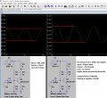
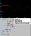
There is a reason why you lose the detected signal when you connect the detector to the amplifier in posting #15. The positive 0.88V base bias at the junction between R1 and R2 is reverse biasing the detector diode. The RF signal is much smaller than that so it will never overcome the bias voltage. That is why you are losing the signal when you connect the diode to the amplifier. Connect a capacitor between the diode and the transistor base to block the DC bias. A 10 uF electrolyitic would work, with the + side connected to the base.
This is a great way to learn about electronics. I did it this way 70 years ago but had to rely on books for my information. I became an Electronics Engineer.
Regards,
Keith
 

Chris65536

Joined Nov 11, 2019
270
I have successfully built some fairly complex digital circuits, but never a crystal radio. I tried many times as a kid, but never heard anything at all. I guess I was too far from the city. Now I have a few more parts in my kit, and an oscilloscope too, so I think I'll try some of the ideas in this thread. Will breadboard work at AM frequencies?
 

MrChips

Joined Oct 2, 2009
34,828
I have successfully built some fairly complex digital circuits, but never a crystal radio. I tried many times as a kid, but never heard anything at all. I guess I was too far from the city. Now I have a few more parts in my kit, and an oscilloscope too, so I think I'll try some of the ideas in this thread. Will breadboard work at AM frequencies?
Breadboard circuit will be fine.

Here are the basic components of a working crystal radio:

1. Long wire aerial
2. Ground connection
3. Coil of wire
4. Variable capacitor
5. Germanium diode
6. High impedance headset

1599752069067.png
 

MrChips

Joined Oct 2, 2009
34,828
Let us discuss how to match the amplifier's output to the loudspeaker.

You might have heard or read about matching the impedance of the driver to that of the load. You may want to do this for two reasons. Firstly, matching the impedance gives you the maximum power transfer from the driver to the load. The second reason for matching the driver to the load is in high frequency transmission lines. We will leave the latter for another discussion.

Another rule of thumb is to make sure that the impedance of the load is much higher (ten times higher) than that of the source. By doing so you minimize the loading effect placed on the driver.

The simplest transistor or tube amplifier is the Class-A amplifier. The transistor is biased in the linear region. The output impedance is relatively high. In order to match the amplifier's output to the load a step-down transformer is often employed. The advantage of this configuration is that it provides both voltage and current gain, i.e. power gain.

1599761714062.png


We will take a different approach by using an emitter follower or common collector circuit configuration.

1599762032699.png

This BJT circuit configuration provides no gain in voltage but it does provide current gain. In other words, the output impedance is relatively low. You can drive a low impedance loudspeaker as in this circuit. However this circuit draws a lot of current and that is the reason Q1 is a TIP31 power transistor.

1599762307077.png

As I am proposing to use a pair of 250Ω headpieces wired in series to give 500Ω, I am going to wire the load directly into the BJT's emitter load.

Emitter Follower AF amp.jpg
The next step is to design a driver stage to drive this output stage.
 

Audioguru again

Joined Oct 21, 2019
6,826
Your power amplifier that uses a BD139 little power transistor has some serious problems:
1) The 500nF input coupling capacitor value is 1000 times too small to pass 1kHz and higher audio since the transistor circuit has an extremely low input impedance. I changed the transistor because my Sim program does non have a BD139 but my replacement transistor works the same.
2) The 22 ohms resistor in series with the speaker attenuates the speaker signal 11.4 times.
3) The maximum output power in the speaker is almost nothing, mostly heat since the speaker has DC in it.
 

Attachments

Thread Starter

Anonymous User 30

Joined Sep 4, 2017
40
Hi All,

Thank you so much for your replies. A lot of food for thought. I will get back to you all once I digest the above and work out where to go from here.
 

Audioguru again

Joined Oct 21, 2019
6,826
Usually we do not match impedances because then it would throw away half the signal level (voltage divider).

The impedance of a coupling capacitor is usually much less than its load resistance.

The parallel coil and tuning capacitor are a very fairly high impedance at resonance so they needs a very high load impedance.

An audio amplifier usually has an output impedance of 0.02 ohms or less to drive a 4 ohm speaker or an output impedance of 0.04 ohms or less to drive an 8 ohm speaker to damp audio resonances. It is called the Damping Factor.
 

Thread Starter

Anonymous User 30

Joined Sep 4, 2017
40
I managed to make improvements with the 2 stage amplifier but its not perfect. Attached is the amplifier schematic for LTspice. I get no gain whatsoever through the first transistor (BC548) but a little gain through the second transistor (BD139). Obviously id like to make full use of the speaker's 6W rms output, but right now its operating at about 0.2 W rms. Enough to hear in a small room. The gain I designed it for is under the transistors, but the actual gain at stages is over on the right.

2 stage BJT.JPG

I think once I get the amplifier working well enough, I will add a potentiometer for volume control and start looking for a suitable enclosure for it to finish the project.
 

Attachments

Thread Starter

Anonymous User 30

Joined Sep 4, 2017
40
The highest impedance you can get your hands on. 600Ω would be nice.

Did you read my post #20?
Thank you for the effort you've taken to help. I really appreciate it.

V Signal * ( Z load / Z source + Z load )

As the source is high Z you need a high load impedance to preserve the signal.

A parallel LC circuit has a very high impedance at resonance as XL - XC = 0.

Anything divided by zero is infinite. Therefore I need a high load impedance.

I'll going to try an source one.
 

MrChips

Joined Oct 2, 2009
34,828
There are alternatives to a high impedance loudspeaker.
If all you have is an 8Ω speaker then possible alternatives are:

1) step down audio transformer
2) Class-B push-pull amplifier
3) LM386 amplifier

Of course, you realize that we have deviated from the true sense of a crystal radio.
While you're at it you may want to look up MK484 radio IC.
 

Audioguru again

Joined Oct 21, 2019
6,826
The audio input signal in your new transistor audio amplifier is at least 1000 times too high at 1MHz.
That is the radio frequency of an AM radio station. Audio frequencies are from 20Hz to 20kHz.
I tested the 1st transistor at 1kHz.

Again, your second transistor is a class-A heater producing low output power but a lot of heat. The 22 ohms resistor in series with the speaker is an attenuator. The biasing resistor values are Way Too low.

Again, you have DC in the speaker which might damage it and cause distortion.

I show your 1st audio transistor with capacitor values increased for 1kHz and it produces severe distortion.
I also show it with a resistor added for negative feedback for low distortion and its load resistance increased.
 

Attachments

MrChips

Joined Oct 2, 2009
34,828
Simple AF push-pull amplifier

I am not going to show you the "best" high-fidelity audio amplifier. What I will show you is a simple audio amplifier that you can assemble and test on a breadboard using commonly available components.

Working from the output back to the input, Q2 and Q3 is a push-pull complementary pair. Each transistor is configured in emitter-follower configuration. This provides current output with low output impedance and hence can drive a low impedance speaker.

C2 couples the AC signal to the speaker while not allowing DC to flow through.

R4 and R5 add a little bit of negative feedback and prevents thermal runaway.

Q1 provides current to drive both Q2 and Q3 which are biased to turn on slightly as in Class-AB and Class-B amplifiers. While this makes for better efficiency, it is a compromise between good linearity and having some cross-over distortion.
Diodes D1 and D2 provide a 2-diode voltage difference between the bases on Q2 and Q3.

Q1 is a common emitter amplifier configuration. Lots of negative feedback is applied via R1 and R3.
Negative feed back is important to avoid thermal runaway and to improve on overall linearity.

VR1 and C1 couples the AC component of the AF input to the base of Q1.

AF push-pull amp.jpg
 

MrChips

Joined Oct 2, 2009
34,828
A word about loudspeakers

A physically large loudspeaker does not necessarily deliver better sound. A large loudspeaker is designed to deliver more power than a smaller speaker. A small speaker requires less current and is more efficient that a larger speaker. You need more power to drive a large speaker.

The speaker is just a transducer and is only half the story. The speaker enclosure is essential to getting good sound from the loudspeaker. A speaker standing alone has poor low frequency output. The back acoustic wave from the speaker cancels the front wave. You get no bass sounds.

The purpose of the speaker enclosure is to prevent the back wave from coming forward.
A simple thing such as mounting the speaker on a wooden panel with a circular hole cut out to fit the speaker will make a world of a difference. This is called a baffle board.

The next step is to install the speaker in a speaker cabinet.

Loudspeaker cabinet design and construction is an entire art and craft in itself.
 

MrChips

Joined Oct 2, 2009
34,828
Hello MrChips,
I simulated your amplifier.
With some obvious output clipping, its output power into an 8 ohm speaker is only 0.019W and it has almost no voltage gain.
I appreciate your input. I don't do a lot of simulation.
I have this circuit on a breadboard driving a 16Ω speaker. The output volume and quality is good enough for output from a crystal radio with additional RF and AF amplification before driving this output stage.
 
Top