Diy sawtooth vco

Thread Starter

rozpalt

Joined Jan 3, 2026
1
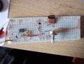
I'm trying to make a VCO from this schematic but I can't get it to work.
My oscilloscope broke so I can't use it but when I plug in my headphones I only hear a slight DC voltage.
(The circuit runs on a single supply)
single_opamp_saw_vco_152.jpg
 

Attachments

Last edited by a moderator:

Alec_t

Joined Sep 17, 2013
15,103
I only hear a slight DC voltage.
? Human hearing doesn't extend down to DC.
Isn't the lower transistor upside down?
What is the value/character of CV-in?
Please get into the habit of adding designators (e.g. R3, C5, Q2) to all circuit components if you want us to discuss your circuits.
Welcome to AAC!
 

lichurbagan

Joined Jul 4, 2025
120
Since you have no oscilloscope, you can test with an LED. You can connect an LED to the OP-AMP output with a series resistor. If there is an oscillation, LED brightness changes with frequency. At low frequency, LED flickers
 

Sinus23

Joined Sep 7, 2013
250
Hello.

The capacitor on the output according to the schematic should block the DC voltage. But where is the output transistor?

BTW the brown wire to the base on the transistor doesn't seem to be connected with the blue wire from the potentiometer. So it looks like the base is floating.
 

MisterBill2

Joined Jan 23, 2018
27,186
The reason for a lack of signal is that the circuit is not oscillating.The OPAMP bias voltages are not right.
It is an attempt to use an opamp as a comparator, in this case to produce ramp waves,
 

Sinus23

Joined Sep 7, 2013
250
The reason for a lack of signal is that the circuit is not oscillating.The OPAMP bias voltages are not right.
It is an attempt to use an opamp as a comparator, in this case to produce ramp waves,
I thought this circuit looked peculiar as well. Looks kind of like a circuit for a modular system since it has a control voltage input but is unipolar running on 9 volts like a guitar pedal.

So I simulated it.
SawWaveOSC.png

It does indeed oscillate, even in simulation, I however had to increase the size of the output capacitor(33u works even better) and put an output buffer so the low impedance of the headphones wouldn´t affect the signal too much.

There are better analog Saw VCO´s out there that are 1V per Oct but they usually need some temperature fluctuation control and careful tuning to be musically useful.

here is a saw core circuit 1V/Oct Simple VCO It uses bipolar voltages though and you kind of can´t get away without using the tempco resistor.
 
Last edited:

MisterBill2

Joined Jan 23, 2018
27,186
Others, in other posts, have been critical of using op-amps as comparators. They were certainly correct!
Simulator circuits often work better than real hardware circuits.
There are quite a few very good VCO circuits around, including some by BOB PEASE and also JIM WILLIAMS, which include descriptions of how they work. The analog design skills of those two were much greater than mine.
 
Top