 Facebook
 Google
 GitHub
 Linkedin
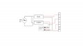
I had a couple of dc power adapters laying around and so i decided to make a bench power supply from them. I used 2 adapters with 12v,1A and 5v,800ma rating. I connected everything as shown in the attached image. The problem is the 12v supply now gives 13v output and 5v supply now gives 6v output. 3.3v seems to be working fine. I could really use some help.
Attachments
-
 82.1 KB Views: 53


