 Facebook
 Google
 GitHub
 Linkedin
Hello guys,
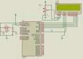
I want to display a message "Hello" on a 16x2 LCD. I am using PIC16F877 and I am programing using assembly language. I used proteus to build or design my project. The LCD does not display the message so I would like you guys help me by looking on what is wrong to my code and my circuit.
my code
On the attachment I have the hex file and the proteus design and the picture of my circuit
I want to display a message "Hello" on a 16x2 LCD. I am using PIC16F877 and I am programing using assembly language. I used proteus to build or design my project. The LCD does not display the message so I would like you guys help me by looking on what is wrong to my code and my circuit.
my code
Rich (BB code):
    list      p=16f877            ; list directive to define processor
 #include <p16f877.inc>        ; processor specific variable definitions

 __CONFIG _CP_OFF & _WDT_OFF & _BODEN_ON & _PWRTE_ON & _RC_OSC & _WRT_ENABLE_ON & _LVP_ON & _DEBUG_OFF & _CPD_OFF
; '__CONFIG' directive is used to embed configuration data within .asm file.
; The lables following the directive are located in the respective .inc file.
; See respective data sheet for additional information on configuration word.


;***** VARIABLE DEFINITIONS
w_temp        EQU     0x7E        ; variable used for context saving
status_temp   EQU     0x7F        ; variable used for context saving
  cblock 0x20
            count            ;used in loops
            count1   ;used in delay routine
   counta   ;used in delay routine
   countb   ;used in delay routine
            templcd ;temp store for 4 bit mode
  endc
LCD_RS Equ 0x04 ;LCD handshake lines
;LCD_RW connected to the ground
LCD_E Equ 0x07


;**********************************************************************
  ORG     0x000             ; processor reset vector
  clrf    PCLATH            ; ensure page bits are cleared
    goto    Main             ; go to beginning of program

  ORG     0x004             ; interrupt vector location
  movwf   w_temp            ; save off current W register contents
  movf STATUS,w          ; move status register into W register
  movwf status_temp       ; save off contents of STATUS register

; isr code can go here or be located as a call subroutine elsewhere

  movf    status_temp,w     ; retrieve copy of STATUS register
  movwf STATUS            ; restore pre-isr STATUS register contents
  swapf   w_temp,f
  swapf   w_temp,w          ; restore pre-isr W register contents
  retfie                    ; return from interrupt


;----------------------------------------------------------------------------------------

;Subroutines:
Init
        clrw                    ; Zero.
        movwf   PORTB      ;resets input/output ports
        bsf     STATUS,RP0      ; Select Bank 1
  movlw   b'00000000'    ; Set port B bits 0-3 as outputs b0-b3 connected to lcd  d4-d7 pins
                                ;and b6-b7 connected to RS,E and RW grounded
        movwf   TRISB        ; Set TRISB register
        bcf     STATUS,RP0      ; Select Bank 0

        retlw 0

LCD_Init
        movlw 0x20   ;Set 4 bit mode
  call LCD_Cmd
        movlw 0x28   ;Set display shift
  call LCD_Cmd
  movlw 0x06   ;Set display character mode
  call LCD_Cmd
  movlw 0x0d   ;Set display on/off and cursor command
  call LCD_Cmd
  call LCD_Clr   ;clear display
  retlw 0x00

LCD_Cmd
        movwf templcd
  swapf templcd, w ;send upper nibble
  andlw 0x0f   ;clear upper 4 bits of W
  movwf PORTB
  bcf     PORTB,LCD_RS ;RS line to 0
  call Pulse_e   ;Pulse the E line high
  movf templcd, w ;send lower nibble
  andlw 0x0f   ;clear upper 4 bits of W
  movwf PORTB
  bcf     PORTB,LCD_RS;RS line to 0
  call Pulse_e   ;Pulse the E line high
  call  Delay5
  retlw 0x00
LCD_CharD addlw 0x30
LCD_Char
      movwf templcd
  swapf templcd,w ;send upper nibble
  andlw 0x0f   ;clear upper 4 bits of W
  movwf PORTB
  bsf     PORTB,LCD_RS   ;RS line to 1
  call Pulse_e   ;Pulse the E line high
  movf templcd,w ;send lower nibble
  andlw 0x0f   ;clear upper 4 bits of W
  movwf PORTB
  bsf     PORTB,LCD_RS   ;RS line to 1
  call Pulse_e   ;Pulse the E line high
  call  Delay5
  retlw 0x00
LCD_Clr
        movlw 0x01   ;Clear display
  call LCD_Cmd
  retlw 0x00
Delay255
        movlw 0xff  ;delay 255 mS
  goto d0
Delay100
     movlw d'100'  ;delay 100mS
  goto d0
Delay50
  movlw d'50'  ;delay 50mS
  goto d0
Delay20
     movlw d'20'  ;delay 20mS
  goto d0
Delay5
  movlw 0x05  ;delay 5.000 ms (4 MHz clock)
d0  movwf count1
d1  movlw 0xC7   ;delay 1mS
  movwf counta
  movlw 0x01
  movwf countb
Delay_0
  decfsz counta, f
  goto $+2
  decfsz countb, f
  goto Delay_0
  decfsz count1 ,f
  goto d1
  retlw 0x00
Text
  addwf PCL, f
  retlw 'H'
  retlw 'e'
  retlw 'l'
  retlw 'l'
  retlw 'o'
  retlw 0x00
Pulse_e
        bsf PORTB,LCD_E
  nop
  bcf PORTB,LCD_E
  retlw 0x00


EndMessage

Stop  goto Stop   ;endless loop


;Program Start:


Main
        call Init
        call Delay100  ;wait for LCD to settle
        call   LCD_Init
        clrf count   ;set counter register to zero
message
        movf count, w  ;put counter value in W
        call Text   ;get a character from the text table
        xorlw 0x00  ;is it a zero?
        btfsc STATUS,Z
  goto EndMessage
        call LCD_Char
        incf count, f
        goto message

ENDAttachments
-
 104.5 KB Views: 83
 -
83.6 KB Views: 40


