Designing a circuit - where to start?

dl324

Joined Mar 30, 2015
16,846
Can someone explain why it woks with reversed polarity with respect to the schematic?
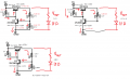
A reversed zener is just diode. It gives you a voltage reference, but it's less stable with current or input voltage changes.
I also suspect that with an even smaller zener, I could get even more range. Which also tells me I haven't understood the circuit, yet.
The range depends on the feedback from the voltage divider on the output.

The purpose of R2 is to bias Q1 on; to the point of saturation without Q2. Q2 takes current from the base of Q1, but the current goes through the zener which is your voltage reference. Zeners have a sharper knee than diodes, so they provide a more stable voltage reference.

Without a zener or diode, you're using the BE junction of Q2. That won't give a very stable reference.
 

Thread Starter

StrongPenguin

Joined Jun 9, 2018
307
I bought a 1,4 V zener, which turned out to be 5,0. Bummer. So my smallest one is still 1,8 V, which gives me about +1 V of regulation. The voltage across the zener is pretty stable (from 1,4 to 2V depending on potmeter setting).

But the funny thing is, that the voltage across my led + resistor varies about 0,2 volts of noise, as if though the zener is not doing it's part.

It still probably too big.

When you say "voltage reference", is that with respect to the regulated output (I.E. Vzener = Vout), or the minimum adjustable voltage?
 

Audioguru

Joined Dec 20, 2007
11,248
A Zener diode with a voltage less than about 4.7V works poorly. Its voltage regulation is poor and its voltage changes when the temperature changes. A Zener diode with a voltage of from 4.7V to 7.5V works best. Its datasheet shows the best voltage.
The current in a Zener diode determines how well it regulates. Some Zener diodes need a low current and others need a high current. Its datasheet shows its best current.

The transistors in this simple circuit also are affected by temperature. A Zener voltage can be selected to cancel the change of voltage caused by the temperature affect on the transistors.

A voltage regulator IC has much better voltage regulation and almost no effect by temperature change than this simple circuit.
 

Thread Starter

StrongPenguin

Joined Jun 9, 2018
307
Well, I tried a lower zener diode, which didn't work. And I can't increase the output voltage, since I get it from my charger. So this setup was doomed to fail, I guess. But I learned stuff. And that is what matters.

Is it possible to just tell me a zener diode value, if I go with a 12 V supply someday? Or do I have to try them all from 1 V and up?
 

dl324

Joined Mar 30, 2015
16,846
Is it possible to just tell me a zener diode value, if I go with a 12 V supply someday? Or do I have to try them all from 1 V and up?
If you're limited to a 5V supply, you can use a forward biased signal diode instead of a zener diode. Regulation will suffer, but that will allow you to experiment with a low voltage power supply.

Go to a second hand store and buy a laptop charger. They're usually around 18V and will supply several amps.
 

PeteHL

Joined Dec 17, 2014
473
The circuit in post #7 also has no short circuit protection, so could zap a transistor if the output is accidentally shorted.

If you use a Sziklai pair (complementary Darlington) as shown below, you can have a maximum output of one base-emitter drop below the input (<1V drop), not two drops as from a standard Darlington.

The PNP must be a power transistor but the NPN an be a standard small transistor.
View attachment 157705
Wow, in all of my decades of perusing circuits on the internet and in print, I have never before come across a Sziklai pair.
 

Thread Starter

StrongPenguin

Joined Jun 9, 2018
307
@dl324 Am I right when I say, that the reason for my circuit not regulating so well, was because due to the low supply voltage, the zener never hit the breakdown region/knee and thus did not conduct enough current? Because with no zener and just a jumper, it is possible to regulate from 0 to 4.2 V.
 

ebeowulf17

Joined Aug 12, 2014
3,307
@dl324 Am I right when I say, that the reason for my circuit not regulating so well, was because due to the low supply voltage, the zener never hit the breakdown region/knee and thus did not conduct enough current? Because with no zener and just a jumper, it is possible to regulate from 0 to 4.2 V.
I believe that regulation is misleading. Usually a regulator compensates for changes in incoming voltage. I think in your modified implementations the output voltage is fairly dependent on input voltage. With a stable supply you can regulate down to a new voltage, but with an unknown or unpredictable supply, output voltage is variable.
 

dl324

Joined Mar 30, 2015
16,846
@dl324 Am I right when I say, that the reason for my circuit not regulating so well, was because due to the low supply voltage, the zener never hit the breakdown region/knee and thus did not conduct enough current? Because with no zener and just a jumper, it is possible to regulate from 0 to 4.2 V.
With the components in your last annotated schematic, Q2 couldn't turn on, so Q1 was saturated. By removing the diode, your voltage reference becomes the BE junction of Q2. The circuit won't regulate well, but you'll be able to adjust the output voltage.
 

dl324

Joined Mar 30, 2015
16,846
Yes, what I was trying to say :p Thanks for all the help. I have closed this case. Fun experience.
Before moving on, try experimenting with this circuit:
upload_2018-11-29_14-19-21.png
If you remove Q2, R2, and R3, Q1 will be saturated and the output will be around 4.3V. Assuming you add a load such as your LED.

With the other components in the circuit, the output voltage would be around 1.4V. Can you determine why?

What would happen if you made R2 twice as large as R3? Then try 3x, 4x, 10x. What happens?
 

ArakelTheDragon

Joined Nov 18, 2016
1,362
I don't want to offend you Mr. Penguin, we can just give you the answer, however jumping from digital to analog electronics will leave you again with a lot of things that you don't know. This is not something to learn for 1 month. It will be best if you ask bertus for some books.
 

Thread Starter

StrongPenguin

Joined Jun 9, 2018
307
No offence taken :) You are right. This thread clearly made me realize that there a some basic stuff, that I need to learn. I really thought this would be a breeze, since I had some (well one course..) electronics in school. I am a maritime engineer by trade, and the few times we are fortunate enough to work with some electrical task, It's mostly 230 V AC. But I still thought I knew stuff.
 

Thread Starter

StrongPenguin

Joined Jun 9, 2018
307
@dl324

1) The circuit measures 1.4 V because the circuit is in balance, both transistors are on, and the voltage drop across each resistor is 0,7 V (don't know any better explanation than this..)

2) If I replace R2 220 Ohm with a potmeter, the Vout increases rapidly until Q1 hits saturation, of around 1,2k Ohm. From 1,2k to 5,5k Ohm yields only a 0.2 V voltage increase.

I'm also having a difficult time determining what region the transistor is in. I can't measure current with the tools I have at the moment, which doesn't make things easier, since the datasheets like current a lot.

What I know:
Vbe = ~ 0,7 V - transistor is on
Vce < 1 V - transistor is saturated

But in the third scenario I get for Q2: Vbe 0,168 V ; Vce = 5,03 V ; Vcb = 4,88 V. Which mode is it in? It doesn't seem to full fill the conditions for cut-off, nor for on mode. I'm going off of this page.

EDIT: Forgot the pic.
 

Attachments

Last edited:

dl324

Joined Mar 30, 2015
16,846
What I know:
Vbe = ~ 0,7 V - transistor is on
Vce < 1 V - transistor is saturated

But in the third scenario I get for Q2: Vbe 0,168 V ; Vce = 5,03 V ; Vcb = 4,88 V. Which mode is it in? It doesn't seem to full fill the conditions for cut-off, nor for on mode. I'm going off of this page.
I don't care for the way that Sparkfun article describes transistor modes.

In the active region, the CB junction is reverse biased and the BE junction is forward biased.

In saturation, both junctions are forward biased.
 

dl324

Joined Mar 30, 2015
16,846
1) The circuit measures 1.4 V because the circuit is in balance, both transistors are on, and the voltage drop across each resistor is 0,7 V (don't know any better explanation than this..)
The way I'd look at it is that R1 wants to saturate Q1, which would cause the output voltage to be around 4.3V. But the voltage divider consisting of R2 and R3 biases Q2 on, which takes some base current from Q1.

Because Q2 is biased on, it's BE junction will be about 0.7V. This will cause the current in R3 to be 0.7V/220 ohms. The current in R2 will be I(R3) + IbQ2. With a sufficiently high beta, base current can be ignored, so the voltage drop across R2 will be the same as R3. That causes the output voltage to be about 2 times Vbe(Q1).

2) If I replace R2 220 Ohm with a potmeter, the Vout increases rapidly until Q1 hits saturation, of around 1,2k Ohm. From 1,2k to 5,5k Ohm yields only a 0.2 V voltage increase.
Based on the analysis for 1) above, Q1 will become saturated when R2 is around 5 times R3.

Another experiment you can do is to change the load current and observe the change in output voltage. Ideally the output voltage wouldn't change when the load changes.

Line and load regulation are two figures of merit for voltage regulators.

Data for LM317:
upload_2018-12-1_10-42-1.png

The simple circuit you're using won't be as good.
 

Thread Starter

StrongPenguin

Joined Jun 9, 2018
307
I have a lot of ground to cover regarding transistors. Great write up.

Q2: Vbe 0,168 V ; Vce = 5,03 V ; Vcb = 4,88 V. One last question. In my datasheet (Fairchild, no idea of the actual transistor maker), I can read in the transfer characteristics, that it's on at Vbe = 0.57 to 0.8 V. What exactly are my readings supposed to tell me? Just that I have a circuit with two busted transistors, not doing much transistor work, but rather just acting as conductors?
 

dl324

Joined Mar 30, 2015
16,846
Q2: Vbe 0,168 V ; Vce = 5,03 V ; Vcb = 4,88 V.
The BE junction needs to be forward biased by about 0.6V before significant collector current can flow. Transistors aren't typically operated in a "slightly" on condition because beta varies with collector current (and Vce, temperature), so in active mode we'd typically bias so Ic is somewhere between 1-20mA.

In the circuit you're working with, collector current can be in the 10's of uA range, but we typically use a value of 0.7V (some use 0.6V) for the BE junction when the transistor is on.
One last question. In my datasheet (Fairchild, no idea of the actual transistor maker), I can read in the transfer characteristics, that it's on at Vbe = 0.57 to 0.8 V. What exactly are my readings supposed to tell me? Just that I have a circuit with two busted transistors, not doing much transistor work, but rather just acting as conductors?
Datasheets typically only give Vbe for saturation mode. In saturation mode, you can think of the transistor as a switch, either being on or off and nothing in between. Transistors are far more interesting and useful when they're operated somewhere between off and on.
 
Top