Select transistors that have voltage, current and power ratings high enough for your project.
The values for the resistors and capacitors are simply calculated by the voltages and currents needed and the datasheets for the transistors.
Although I tend to agree with others that starting with a parts list and trying to divine the schematic is probably not the best approach, nevertheless, I'll honor the original request.
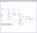
I've come up with a home-spun LDO regulator that seems to work reasonably well in simulation. It has only 7mV dropout at 100mA, and 97mV dropout at 1A, so when you want the full 12V, instead of getting 11.3V with a BJT solution, you can get 11.9 to 11.99V with this circuit. I'm attaching the schematic and LTspice files for those who are interested, but if the thread starter wants to try the original challenge, he can use just the BOM below.
The MOSFET wasn't chosen very carefully - I just took one from the LTspice library that had reasonably low gate charge. There are probably better MOSFET choices, but I think the basic architecture of this circuit works regardless of specific MOSFET selection - the choice would be made based on current requirements, available space, heat sinking, etc.
And here's a graph showing voltage output vs. current for 12V max and 10V output settings:
Your circuit has horrible or none voltage regulation.
Will it blow up if overloaded?
Will it blow up if it over heats?
A voltage regulator IC has excellent voltage regulation and overload and over heat protection in it.
Your circuit has horrible or none voltage regulation.
Will it blow up if overloaded?
Will it blow up if it over heats?
A voltage regulator IC has excellent voltage regulation and overload and over heat protection in it.
I thought it was well established that an IC is far superior. This was meant to be an exercise in seeing what can be whipped up without using a voltage regulator IC. I'm well aware that this lacks protections that IC regulators include.
Having said that, I played around with several variations on where to put the resistor which prevents oscillations, and I realize the version I posted isn't the best. Here's an improved circuit (still missing the protections that an IC regulator has, but with better regulation) using the same parts list. Dropout voltage when trying to hold 12V is similar, but 10V setting performance is much better. I just needed to include the resistor within the feedback loop.
***EDIT: Note that the extra resistor can be omitted entirely, depending on the ESR of the capacitor, but it seems (at least in simulation) like having a resistor somewhere in series with the load provides more foolproof protection against oscillations, whereas relying on the ESR to prevent oscillations is a little more finicky about the exact resistance value.
@ebeowulf17 Great work! You are right, my main objective is to learn. I am in the middle of chewing through the circuit @dl324 provided, just to improve my analyzing skills, then I will look at the one you came with, as it looks like it's on another level.
@ebeowulf17 Great work! You are right, my main objective is to learn. I am in the middle of chewing through the circuit @dl324 provided, just to improve my analyzing skills, then I will look at the one you came with, as it looks like it's on another level.
Yeah, l actually need to go back and take a closer look at the dl324 circuit, cause I don't entirely understand it yet. It may well be a better circuit in many/most ways. The only distinct advantage of the one I posted is the very low dropout spec (the ability to deliver very close to 12V output with 12V supply voltage.)
Have fun analyzing these circuits - I certainly do! I still have a LOT to learn, so if anything about my circuit seems wrong... it probably is wrong. I'm just working through puzzles trying to learn.
Yes. I didn't notice that the three resistors on the right weren't labeled. You can refer to them, from top to bottom, as R3-R5 and R4 would be the potentiometer.
Some earlier circuit suggestions only used a pot. There's an advantage to using 3 resistors. Can think of reasons why you would, or wouldn't, want them?
@ebeowulf17 I am indeed having fun. Never really analyzed anything with transistors before, so this is a fun challenge.
@dl324 No I haven't quite figured out the whole mechanism of the circuit yet. But I will. I'm used to being supplied a few values when analyzing, so this is new.
No I haven't quite figured out the whole mechanism of the circuit yet. But I will. I'm used to being supplied a few values when analyzing, so this is new.
Please see post #19 by @dl324, since I'm not on my computer and can't save the image to repost it here.
I finally got around to playing with this circuit. And It won't work. It's either/or. If i use R2 = 0 to 1k ohm, the LED lights up, higher and it turns off.
First I tried with just all 1k resistors, which turned the LED on. I also got a 1k potmeter, which makes no difference since It's out of play.
I tried to calculate the R2 bias resistor using the formula on this page: R2 = (Vbb - Vbe) / ( Ic / Beta), which gave me 1,3M. A lot more than my 1k. Yikes.
Values were Vbb = 5 Vdc, Vbe = 0.7 V, Ic = 1 mA, Beta = 325 (middle value of a 547B transistor)
There are a few more things I don't understand. If a transistor is just an on/off switch, then how can it be used to regulate voltages in this circuit?
The zener diode, is it only used for limiting maximum output voltage?
There are a few more things I don't understand. If a transistor is just an on/off switch, then how can it be used to regulate voltages in this circuit?
I know there are about a million articles on voltage regulators, but I am more looking for the board design process, with the purpose of building and designing a regulator my self.
If you want to learn how to design a voltage regulator, the schematic you referenced is a basic circuit. It's the first one I built in school.
If you want to use an LM317, there's really no design involved. You add a couple resistors and a couple caps and you're done. The only drawback is that you need a negative supply if you want to be able to adjust to zero. The datasheet has an example and the ATX has a -5V output.
Ok. When I tried to play around with digital gate circuits, I just took an output, and worked from there, knowing nothing about the wonders of Kmaps and Boole.
Now I want to design a voltage regulator to my ATX power supply, from 0V to 12V (or 24V, if that is possible..)
I know there are about a million articles on voltage regulators, but I am more looking for the board design process, with the purpose of building and designing a regulator my self.
Where do I start? I have a (two, actually..) 741 op-amp, could I use it for this purpose?
All the ATX PSUs I've encountered need both 3.3V & 5V outputs loaded or the PWM controller just charges up the output caps and settles back to idle - the other output will collapse if you load them without attending to that requirement. The one I reverse engineered had the 3.3V & 5V outputs resistor summed into a single TL431 regulator.
Using boost converters might be a convenient way to load the 3.3 & 5, linears to get intermediate voltages from the boost rails would be a good way of keeping them busy.
Here are the measurements. The (maybe not so) funny thing is that if I remove Q2, nothing happens. Nor does it affect the circuit if adjust the potmeter knob.
@dl324 I do wan't to work with some circuit design, or at least have a basic grasp of it. And this circuit is a good start, indeed. But I also wan't a variable bench supply, which thought the mentioned basic circuit was. Just to clear things up, what exactly is the function of the potmeter?
@ian field I moved from the ATX supply to something (hopefully) more simple. It was heavy as a brick. As of now, I just want this 5 Vdc regulator to work, getting the supply from my laptop.
Your circuit does not work because the input voltage is too low. The input voltage must be much higher than the Zener diode voltage, or use a lower voltage Zener diode.
There are a few more things I don't understand. If a transistor is just an on/off switch, then how can it be used to regulate voltages in this circuit?
Tried with another zener, and it worked! And then I realized I had connected the cathode (black stripe, right?) to ground. So I had to try cathode grounded with the other zeners (only have three, they are 2.2, 3.8, and 5 V IIRC, can't tell which one is which..). Lo and behold, they all worked now.
There was just a difference in voltage regulation. I did some new measurements of the best one. Can someone explain why it woks with reversed polarity with respect to the schematic? I also suspect that with an even smaller zener, I could get even more range. Which also tells me I haven't understood the circuit, yet.
EDIT: Works best with 1.8V Zener.
EDIT2: And with no zener, I can regulate down to 0 V. And the zener cathode grounded worked because it was acting just as a jumper.
 Facebook
 Google
 GitHub
 Linkedin