Design Help with a Electrometer circuit

Thread Starter

geobabu

Joined Aug 13, 2008
6
Hi,
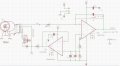
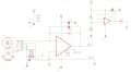
I was trying to draw a electrometer circuit for a pico amp sensing from an Ionizing chamber, which is connected through a triax connector. The center guard ring is supplied with the biasing voltage that can be upto 500VDC. After referring through various design documents , really confusions gone worst. I am seeking help to complete this. As a beginning its drawn a rough schematic. Please guide through this .
 

Attachments

Thread Starter

geobabu

Joined Aug 13, 2008
6
Yes, Sorry Its LMP7721 opamp. Even though its drawn like, I really doubt whether its a correct circuit. Connecting the high volt VBias to the virtual GND and Opamp INV input, is really really necessary here or it may end in a catastrophic failure ?!!.
 

Janis59

Joined Aug 21, 2017
1,894
RE:"" or it may end in a catastrophic failure""
It would be wise to put any voltage limiter at transimpedance amplifier input. As the Zeners has too large current, the best choice may stand CG75L or sth like that (memorize this very useful part) - it is well recommended for electrometric inputs where the current via it is an order of 75 fA (R>10^13 Ohm).
By the way, I like the 7721 because it`s price too, but I KNOW it is so cheap only for one reason - it`s input data are NOT warranted. Some have, some not, into comparison with, for example AD515 AD549 and many many more. Probably You have problem because of such `non guaranteed` one??
More, it is enormous important the insulator material of input wires. Most of materials are or triboelectric, or piezoelectric, or at least hygroscopic, or all that together. Therefore ALL good insulators are wrong choice when talk is about 60 separate electrons caching (what is limit for 7721), and especially bad is the (surpriiize!) teflon, however good is (more surpriiize!) PVC, however it resistance is 2-3 orders worser, thus it must be long enough . Read more about insulators allowable at datasheet of AD549, and best if use a air-hang mounting style. No any PCB is categorical demand if not loose all sensitivity You have. Probably, better habits has a Rogers inc teflon-based pcb~s but anyway triboeffect will kill Your brain, and them are not cheap indeed.
And last, I read a Paton institute certain article from Kiiv, what motivated that two-transistor simple amplifier are capable to overbeat any most best opamp with only demanded some quirks: they used BC549 those with a smallest noise factor (0,4 dB) and picked out of the 1000 bjt box the two best for this Fn value, what was roughly about Fn=0,1 dB. In the result, they applied it to pin diode what allowed to see ONE ALONE particle cached by diode p/n barrier. Well well, that is sensitivity of dreams indeed, but we have an opamp.
Thus, the noise factor is not less important as input current. However I see You use an enormously large integrator 100 pF, normally it is few pF or maybe 10. It means You need no a fast reaction, seems.
And last, all circuits I had an ocassion to work with, had a resistor in series with `hot` input wire, let say 1K or 10K. Firstly, it stabilizes the Gain, secondly- it saves the input it case of 500V tries to beat it out.
 
Last edited:

Thread Starter

geobabu

Joined Aug 13, 2008
6
RE:"" or it may end in a catastrophic failure""
It would be wise to put any voltage limiter at transimpedance amplifier input. As the Zeners has too large current, the best choice may stand CG75L or sth like that (memorize this very useful part) - it is well recommended for electrometric inputs where the current via it is an order of 75 fA (R>10^13 Ohm).
By the way, I like the 7721 because it`s price too, but I KNOW it is so cheap only for one reason - it`s input data are NOT warranted. Some have, some not, into comparison with, for example AD515 AD549 and many many more. Probably You have problem because of such `non guaranteed` one??.
Thank you Janis, for giving valuable inputs. When I studied more about the sensor it found that , the VBias is required to the outer layer and the middle ring is with the ground. So I redrawn as a transimpedance amplifier, along with another opamp. which act as a guard ring and driver . Hope it may clears the most of input cable related issues pointed out. I had selected the LMP7721, due to its availability and cost. I just checked about AD549 opamp, really huge price is seen and its almost x30 times more than LMP7721.

Since we need to sense the pico amp range current , the 10M resistor, is removed , because its really require a > 10^13 as previously pointed out and they are difficult to available. But got the doubt that , what should be ref. resistance value need to consider in this Vout = - Iin * R ?
And since I am looking for almost real time capture , the integrator cap. value is reduced to 1pF or even smaller if its available.
a 1 Mohm / 0.1% resistance is added to the Input line as a protection, really this bigger value can cause unexpected issues ?
I am submitting the redrawn circuit for a review. Really the PCB designing is going to a challenge !!
Once again , thank you for your time.
 

Attachments

Top